Toshiba Tecra M9-S5516X User Guide - Page 51
Place the screw and the cover in a safe place so that you can, retrieve them later.
 |
View all Toshiba Tecra M9-S5516X manuals
Add to My Manuals
Save this manual to your list of manuals |
Page 51 highlights
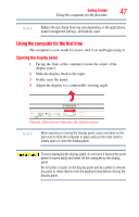
Getting Started 51 Adding memory (optional) 5 Close the display panel and turn the computer upside down to locate the memory module slot cover. Memory module slot cover Front of computer (Sample Illustration) Locating the memory module slot cover 6 Using a small Phillips screwdriver, loosen the captive screw that secures the memory module slot cover. Back of computer (Sample Illustration) Removing the memory module slot cover 7 Remove the memory module slot cover. 8 Place the screw and the cover in a safe place so that you can retrieve them later. Static electricity can damage the memory module. Before you handle the module, touch a grounded metal surface to discharge any static electricity you may have built up.
-
 1
1 -
2
-
3
-
4
-
5
-
6
-
7
-
8
-
9
-
10
-
11
-
12
-
13
-
14
-
15
-
16
-
17
-
18
-
19
-
20
-
21
-
22
-
23
-
24
-
25
-
26
-
27
-
28
-
29
-
30
-
31
-
32
-
33
-
34
-
35
-
36
-
37
-
38
-
39
-
40
-
41
-
42
-
43
-
44
-
45
-
 46
46 -
 47
47 -
 48
48 -
 49
49 -
 50
50 -
 51
51 -
 52
52 -
 53
53 -
 54
54 -
 55
55 -
 56
56 -
57
-
58
-
59
-
60
-
61
-
62
-
63
-
64
-
65
-
66
-
67
-
68
-
69
-
70
-
71
-
72
-
73
-
74
-
75
-
76
-
77
-
78
-
79
-
80
-
81
-
82
-
83
-
84
-
85
-
86
-
87
-
88
-
89
-
90
-
91
-
92
-
93
-
94
-
95
-
96
-
97
-
98
-
99
-
100
-
101
-
102
-
103
-
104
-
105
-
106
-
107
-
108
-
109
-
110
-
111
-
112
-
113
-
114
-
115
-
116
-
117
-
118
-
119
-
120
-
121
-
122
-
123
-
124
-
125
-
126
-
127
-
128
-
129
-
130
-
131
-
132
-
133
-
134
-
135
-
136
-
137
-
138
-
139
-
140
-
141
-
142
-
143
-
144
-
145
-
146
-
147
-
148
-
149
-
150
-
151
-
152
-
153
-
154
-
155
-
156
-
157
-
158
-
159
-
160
-
161
-
162
-
163
-
164
-
165
-
166
-
167
-
168
-
169
-
170
-
171
-
172
-
173
-
174
-
175
-
176
-
177
-
178
-
179
-
180
-
181
-
182
-
183
-
184
-
185
-
186
-
187
-
188
-
189
-
190
-
191
-
192
-
193
-
194
-
195
-
196
-
197
-
198
-
199
-
200
-
201
-
202
-
203
-
204
-
205
-
206
-
207
-
208
-
209
-
210
-
211
-
212
-
213
-
214
-
215
-
216
-
217
-
218
-
219
-
220
-
221
-
222
-
223
-
224
-
225
-
226
-
227
-
228
-
229
-
230
-
231
-
232
-
233
-
234
-
235
-
236
-
237
-
238
-
239
-
240
-
241
-
242
-
243
-
244
-
245
-
246
-
247
-
248
-
249
-
250
-
251
-
252
-
253
-
254
-
255
-
256
-
257
-
258
-
259
-
260
-
261
 |
 |

51
Getting Started
Adding memory (optional)
5
Close the display panel and turn the computer upside down to
locate the memory module slot cover.
(Sample Illustration) Locating the memory module slot cover
6
Using a small Phillips screwdriver, loosen the captive screw
that secures the memory module slot cover.
(Sample Illustration) Removing the memory module slot cover
7
Remove the memory module slot cover.
8
Place the screw and the cover in a safe place so that you can
retrieve them later.
Static electricity can damage the memory module. Before you handle
the module, touch a grounded metal surface to discharge any static
electricity you may have built up.
Front of computer
Memory module
slot cover
Back of computer