ViewSonic PJ755D Service Manual - Page 4
Table of Contents - lamp
 |
UPC - 766907071917
View all ViewSonic PJ755D manuals
Add to My Manuals
Save this manual to your list of manuals |
Page 4 highlights
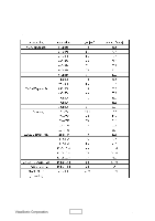
Table of Contents Chapter 1 Introduction 1-1 Product Highlight 1-1 Optical Specification 1-2 Electrical Specification 1-2 Mechanical Specification 1-3 Environment 1-3 Compatible Modes 1-4 Chapter 2 Disassembly of Procedure 2-1 Disassemble Lamp Module and Elevator Foot 2-1 Disassemble Top Cover and Keypad Board 2-2 Disassemble Main Board Module, Wind Tunnel Module and Fan Guider Module 2-4 Disassemble Lamp Driver Module, LVPS Module and Axial Fan 92*25 Module 2-5 Disassemble Color Wheel, Photo Sensor Board, Optical Engine Module and Blower Fan 60*25 Module 2-7 Disassemble Rear Cover, Speaker, Blower Fan 50*20, Thermal Sensor Board, Interrupt Switch Module and Bottom Cover 2-9 Chapter 3 Troubleshooting 3-1 Equipment Needed 3-1 Main Procedure 3-2 Chapter 4 Function Test and Alignment Procedure 4-1 Product 4-1 Test Equipment 4-1 Test Condition 4-1 Test Display Modes and Pattern 4-2 Inspection Procedure 4-8 Chapter 5 Firmware Upgrade Procedure 5-1 Equipment Needed 5-1 Hardware Setup Procedure 5-1 Firmware Program Installation Procedure 5-2 ii PJ755D
-
 1
1 -
 2
2 -
 3
3 -
 4
4 -
 5
5 -
 6
6 -
 7
7 -
 8
8 -
 9
9 -
 10
10 -
11
-
12
-
13
-
14
-
15
-
16
-
17
-
18
-
19
-
20
-
21
-
22
-
23
-
24
-
25
-
26
-
27
-
28
-
29
-
30
-
31
-
32
-
33
-
34
-
35
-
36
-
37
-
38
-
39
-
40
-
41
-
42
-
43
-
44
-
45
-
46
-
47
-
48
-
49
-
50
-
51
-
52
-
53
-
54
-
55
-
56
-
57
-
58
-
59
-
60
-
61
 |
 |