ViewSonic PJ755D Service Manual - Page 41
Setup Procedure, Fixture 1
 |
UPC - 766907071917
View all ViewSonic PJ755D manuals
Add to My Manuals
Save this manual to your list of manuals |
Page 41 highlights
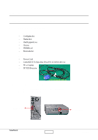
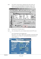
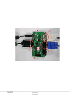
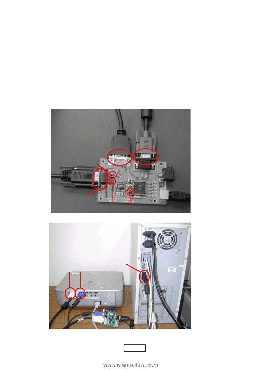
6-2 Setup Procedure 6-2.1 Fixture 1 Step1. Step2. Step3. Step4. Step5. Step6. Connect Power Adapter with fixture. Make sure the JP1and JP5 are closed and JP2 is open. Connect P2 of the fixture with VGA Port of PJ755D by the VGA Cable. Connect P3 of the fixture with DVI Port of PJ755D by the DFP to DVI cable. Connect P4 of the fixture with COM Port of PC by the RS232 Cable. Turn on the power of the fixture. P3 P2 JP1 P4 JP2 JP5 DVI VGA COM1 ViewSonic Corporation 6-2 PJ755D
-
 1
1 -
2
-
3
-
4
-
5
-
6
-
7
-
8
-
9
-
10
-
11
-
12
-
13
-
14
-
15
-
16
-
17
-
18
-
19
-
20
-
21
-
22
-
23
-
24
-
25
-
26
-
27
-
28
-
29
-
30
-
31
-
32
-
33
-
34
-
35
-
 36
36 -
 37
37 -
 38
38 -
 39
39 -
 40
40 -
 41
41 -
 42
42 -
 43
43 -
 44
44 -
 45
45 -
 46
46 -
47
-
48
-
49
-
50
-
51
-
52
-
53
-
54
-
55
-
56
-
57
-
58
-
59
-
60
-
61
 |
 |
PJ755D
6-2
ViewSonic
Corporation
6-2
Setup Procedure
Step1.
Connect Power Adapter with fixture.
Step2.
Make sure the JP1and JP5 are closed and JP2 is open.
Step3.
Connect P2 of the fixture with VGA Port of PJ755D by the VGA Cable.
Step4.
Connect P3 of the fixture with DVI Port of PJ755D by the DFP to DVI cable.
Step5.
Connect P4 of the fixture with COM Port of PC by the RS232 Cable.
Step6.
Turn on the power of the fixture.
P3
P2
JP5
JP1
JP2
P4
6-2.1
Fixture 1
COM1
DVI
VGA