Weider 7400 Weight English Manual - Page 8
The teeth
 |
View all Weider 7400 Weight manuals
Add to My Manuals
Save this manual to your list of manuals |
Page 8 highlights
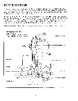
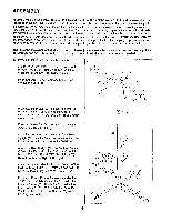
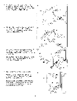
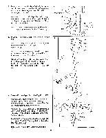
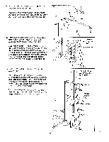
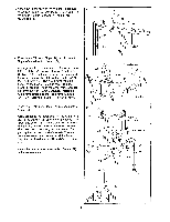
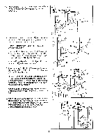
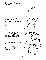
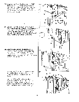
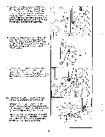
13. Attach the upper ends of the Weight Guides (72) 13 to the Top Frame (67) with the 5/16" x 6" Bolt (74), the two 1/2" x 3/4" Spacers (73) and a 5/16" Nylock Nut (3). 73 72 3 67 74 72 ••= 5E>.• 14. Press two 1 3/4" Inner Caps (44) and 1" Round Caps (49) into the Arm Frame (52). Apply grease to the upper axle on the Arm Frame (52). Hold the axle between the two Arm Frame Bushings (68). Set the Arm Frame Bushings and the Arm Frame on the plate welded to the top of the Top Frame (67). The Arm Frame must be turned so the bracket is facing away from the Front Upright (42). Place the Arm Frame Bracket (69) over the Arm Frame Bushings. Attach the Arm Frame Bracket to the Top Frame with four 1/4" x 3/4"' Screws (18) and 1/4" Nylock Nuts (7). 15. Press two 1 3/4" Inner Caps (44) into each of the Arms (46). Apply grease to the lower axles on the Arm Frame (52). Slide an Arm (46) onto one of the axles. The upper end of the Arm must be between the Front Upright (42) and the bracket on the Arm Frame. Hold two 1" Retainers (54) and a 1" Round Cap (55) against the lower end of the axle. The teeth on the Retainers must bend toward the Round Cap. Tap the Retainers and Round Cap onto the axle. Attach the other Arm (46) to the Arm Frame (52) in the same manner. 14 7 69 67 52-G rease 68 49 49 44 42 15 44 18 Bracket Bracke 42 44 52-Grease Grease 54 46 44 55 54 55 46 44 a 8
-
 1
1 -
2
-
 3
3 -
 4
4 -
 5
5 -
 6
6 -
 7
7 -
 8
8 -
 9
9 -
 10
10 -
 11
11 -
 12
12 -
 13
13 -
14
-
15
-
16
-
17
-
18
-
19
-
20
 |
 |
