Weider Cobra 1000 English Manual - Page 7
throe 9, PrAtitnro, rn;_le 9g
 |
View all Weider Cobra 1000 manuals
Add to My Manuals
Save this manual to your list of manuals |
Page 7 highlights
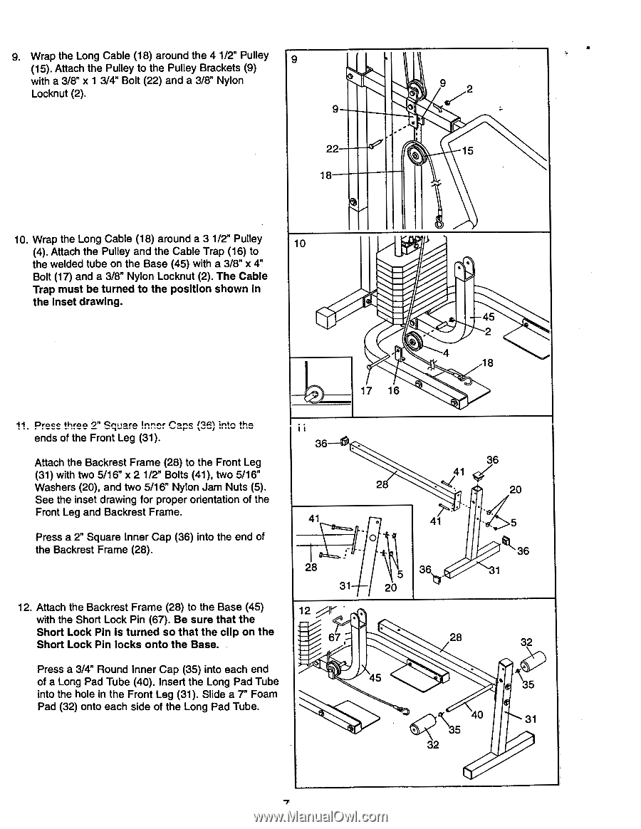
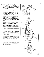
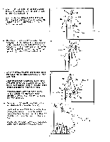
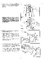
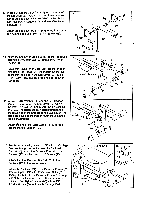
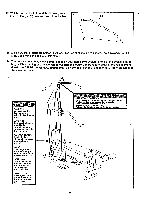
9. Wrap the Long Cable (18) around the 4 1/2" Pulley 9 (15). Attach the Pulley to the Pulley Brackets (9) with a 3/8" x 1 3/4" Bolt (22) and a 3/8" Nylon Locknut (2). 9 22 I 18 . 9 2 o . t 15 10. Wrap the Long Cable (18) around a 3 1/2" Pulley (4). Attach the Pulley and the Cable Trap (16) to 10 the welded tube on the Base (45) with a 3/8" x 4" Bolt (17) and a 3/8" Nylon Locknut (2). The Cable Trap must be turned to the position shown in the inset drawing. 1 17 16 45 , 2 4 .18 11 prnee throe 9" PrAtitnro Inner rn;_le (9g) :intr, the, ends of the Front Leg (31). Attach the Backrest Frame (28) to the Front Leg (31) with two 5/16" x 2 1/2" Bolts (41), two 5/16" Washers (20), and two 5/16" Nylon Jam Nuts (5). See the inset drawing for proper orientation of the Front Leg and Backrest Frame. Press a 2" Square Inner Cap (36) into the end of the Backrest Frame (28). 12. Attach the Backrest Frame (28) to the Base (45) with the Short Lock Pin (67). Be sure that the Short Lock Pin is turned so that the clip on the Short Lock Pin locks onto the Base. Press a 3/4" Round inner Cap (35) into each end of a Long Pad Tube (40). Insert the Long Pad Tube into the hole in the Front Leg (31). Slide a 7" Foam Pad (32) onto each side of the Long Pad Tube. i i 36-0 28 36 41 ,c( 20 41 . • O ,- - 28 5 31 20 12 .„. --0-- • 67 . • 41 36 28 . 45 5 36 32 . 35 \ 40 31 . 5 32 7
-
 1
1 -
 2
2 -
 3
3 -
 4
4 -
 5
5 -
 6
6 -
 7
7 -
 8
8 -
 9
9 -
 10
10 -
 11
11 -
 12
12 -
13
-
14
-
15
-
16
-
17
-
18
-
19
-
20
 |
 |