Weider Cobra 1000 English Manual - Page 8
Weider Cobra 1000 Manual
 |
View all Weider Cobra 1000 manuals
Add to My Manuals
Save this manual to your list of manuals |
Page 8 highlights
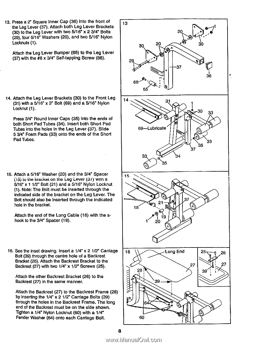
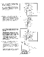
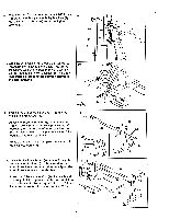
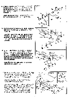
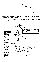
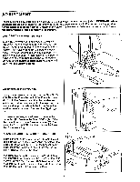
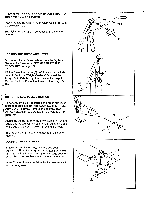
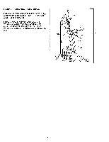
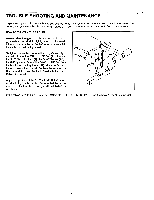
13. Press a 2" Square Inner Cap (36) into the front of the Leg Lever (37). Attach both Leg Lever Brackets (30) to the Leg Lever with two 5/16" x 2 3/4" Bolts (29), four 5/16" Washers (20), and two 5/16" Nylon Locknuts (1). Attach the Leg Lever Bumper (65) to the Leg Lever (37) with the #8 x 3/4" Self-tapping Screw (66). 14. Attach the Leg Lever Brackets (30) to the Front Leg (31) with a 5/16" x 3" Bolt (69) and a 5/16" Nylon Locknut (1). Press 3/4" Round Inner Caps (35) into the ends of both Short Pad Tubes (34). Insert both Short Pad Tubes into the holes in the Leg Lever (37). Slide 5 3/4" Foam Pads (33) onto the ends of the Short Pad Tubes. 15. Attach a 5/16" Washer (20) and the 3/4" Spacer (i9) io the brackei on the Leg Lever (Jo with a 5/16" x 1 1/2" Bolt (21) and a 5/16" Nylon Locknut (1). Note: The Bolt must be inserted through the indicated side of the bracket on the Leg Lever. The Bolt should also be inserted through the indicated hole in the bracket. Attach the end of the Long Cable (18) with the shook to the 3/4" Spacer (19). 13 3 o is_..-71 20 A - 4 , 20 $ 30 A , , • 29 to„,,, o 37 c i, 3 6 6' : 6 14 31 1 - • 30 33 0 - c• 69-Lubricate 3 0 35 IA , o 33 35 37 4 15 \\. 37 21 18 ..... o 1 N 16. See the inset drawing. Insert a 1/4" x 2 1/2" Carriage 16 Bolt (39) through the centre hole of a Backrest Bracket (26). Attach the Backrest Bracket to the Backrest (27) with two 1/4" x 1/2" Screws (25). 28 Attach the other Backrest Bracket (26) to the Backrest (27) in the same manner. Long End 25 26 4.". 27 . 27 3 ,. 39 Attach the Backrest (27) to the Backrest Frame (28) by inserting the 1/4" x 2 1/2" Carriage Bolts (39) through the holes in the Backrest Frame. The long end of the Backrest must be on the side shown. 64 • Tighten a 1/4" Nylon Locknut (60) with a 1/4" Fender Washer (64) onto each Carriage Bolt. 60 8
-
 1
1 -
2
-
 3
3 -
 4
4 -
 5
5 -
 6
6 -
 7
7 -
 8
8 -
 9
9 -
 10
10 -
 11
11 -
 12
12 -
 13
13 -
14
-
15
-
16
-
17
-
18
-
19
-
20
 |
 |