Weider Pro 450 English Manual - Page 9
Lubricate the M10 x 155mm Bolt 22. Slide the Bolt
 |
View all Weider Pro 450 manuals
Add to My Manuals
Save this manual to your list of manuals |
Page 9 highlights
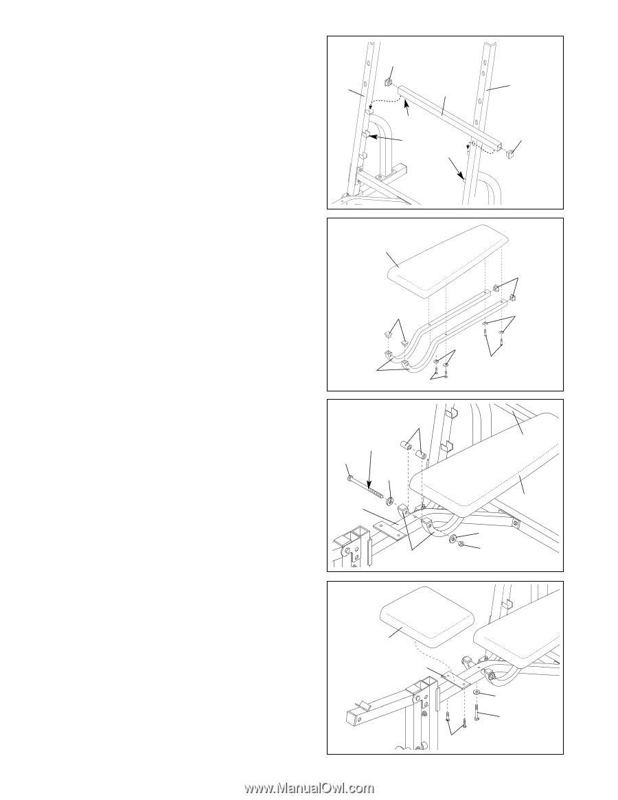
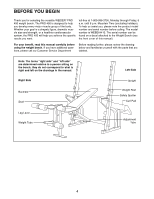
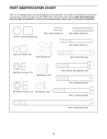
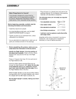
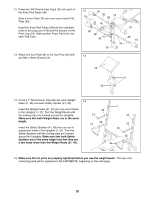
8. Press a 30mm Square Inner Cap (40) into each end 8 of the Adjustment Tube (29). Place the Adjustment Tube (29) in one set of adjust- ment brackets on the Uprights (1, 37). Make sure 1 that the pins on the Adjustment Tube are inserted into the slots in the adjustment brackets. 40 29 Pin Adjustment Brackets 37 40 9. Press 1" Square Inner Caps (28) into the ends of both 9 Backrest Tubes (27). 15 Attach the Backrest Tubes (27) to the Backrest (15) with four M6 x 38mm Screws (4) and four M6 28 Washers (30). Do not tighten the four Screws yet. 28 30 10. Rest the Backrest (15) on the Adjustment Tube (29). Lubricate the M10 x 155mm Bolt (22). Slide the Bolt through an M10 Washer (6), the right Backrest Tube (27), a 16mm x 18.5mm Spacer (8), and the Bench Frame (5), so that the tip of the Bolt is barely visible on the other side. Hold another 16mm x 18.5mm Spacer (8) between the Bench Frame (5) and the left Backrest Tube (27). Slide the M10 x 155mm Bolt (22) through the Spacer and the left Backrest Tube. Secure the Bolt with an M10 Washer (6) and an M10 Nylon Locknut (11). Do not overtighten the Nylon Locknut; the Backrest must be able to pivot freely. Tighten the four M6 x 38mm Screws (4) used in step 9. 27 4 10 8 Lubricate 22 6 5 27 11 30 4 29 15 6 11 11. Attach the Seat (14) to the Bench Frame (5) with two M6 x 16mm Screws (3), an M6 x 62mm Screw (7), and an M6 Washer (30). 14 5 30 7 3 9
-
 1
1 -
2
-
3
-
 4
4 -
 5
5 -
 6
6 -
 7
7 -
 8
8 -
 9
9 -
 10
10 -
 11
11 -
 12
12 -
 13
13 -
 14
14 -
15
-
16
-
17
-
18
 |
 |