Weider X2 Uk Manual
Weider X2 Manual
 |
View all Weider X2 manuals
Add to My Manuals
Save this manual to your list of manuals |
Weider X2 manual content summary:
- Weider X2 | Uk Manual - Page 1
4 Revie Road Industrial Estate Revie Road Beeston Leeds LS118JG UK email: [email protected] CAUTION Read all precautions and instructions in this manual before using this equipment. Save this manual for future reference. ® USERʼS MANUAL Patent Pending w Visit our website at www.weiderfitness.com - Weider X2 | Uk Manual - Page 2
Diagram 16 Adjustment 17 Weight Resistance Chart 18 Maintenance and Trouble-shooting 19 Part Identification Chart End of Manual Part List End of Manual Exploded Drawing End of Manual How to Order Replacement Parts Back Cover WEIDER is a registered trademark of ICON Health & Fitness, Inc - Weider X2 | Uk Manual - Page 3
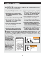
responsibility of the owner to ensure that all users of the training system are adequately informed of all precautions. 2. Read all instructions in this manual and in the accompanying literature before using the training system. 3. If you feel pain or dizziness while exercising, stop immediately and - Weider X2 | Uk Manual - Page 4
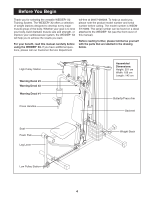
for selecting the versatile WEIDER® X2 Training System. The WEIDER® X2 offers a selection system, the WEIDER® X2 will help you to achieve the results you want. For your benefit, read this manual carefully before using the WEIDER® X2. If you have additional questions, please call our Customer Service - Weider X2 | Uk Manual - Page 5
training system, make sure that all parts are oriented exactly as shown in the drawings. Tightening Parts Tighten all parts as you assemble them, unless instructed to do otherwise. Questions? If you have questions after reading the assembly instructions, please call our Customer Service Department - Weider X2 | Uk Manual - Page 6
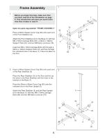
(1) with two M8 x 70mm Carriage Bolts (64), a 50mm x 102mm 2 Support Plate (21), and two M8 Nylon Locknuts (70). Insert two M8 x 70mm Carriage Bolts (64) through a 50mm x 102mm Support Plate (21) and then through the indicated holes in the Base (1). Place the - Weider X2 | Uk Manual - Page 7
Nylon Locknut (70) onto each Carriage Bolt. Do not tighten the Nylon Locknuts yet. 3 Support Tube 39 4 70 70 4. Place the Weight Bumpers (44) over the outer holes in of Weight Plates (36). Slide the Top Weight (17) onto the Weight Guides (13). Make sure that the groove in one side of the Top - Weider X2 | Uk Manual - Page 8
to the Rear Upright (5) with two M8 x 70mm Carriage Bolts (64), a 50mm x 102mm Support Plate (21), and two M8 Nylon Locknuts (70). Fully tighten all Nylon Locknuts used in steps 2 and 3. 6 6. Attach one Weight Guide (13) to the indicated bracket on the Top Frame (6) with an M8 x 38mm Bolt (67 - Weider X2 | Uk Manual - Page 9
65mm Bolt (58). Attach the Locking Plate to the indicated hole in the support tube with the Bolt, two M10 Flat Washers (62), and an M10 the Right Arm (11) with two M8 x 60mm Carriage Bolts (65), a 38mm x 102mm Support Plate (22), and two M8 Nylon Locknuts (70). Press a 25mm Round Inner Cap (41) into - Weider X2 | Uk Manual - Page 10
11. Insert the round tube on the Right Arm (11) into the indicated hole in the Butterfly/Press Frame (9). While a second person holds the Right Arm, place a 25mm Washer (85) over the tube on the Right Arm. Attach the Right Arm with an M6 x 35mm Screw (77) and an M6 Nylon Locknut (79). Press a 25mm - Weider X2 | Uk Manual - Page 11
15. Wrap the Butterfly Cable (47) around a 90mm Pulley 15 (50) in the direction shown. Attach the Pulley and two Pulley Covers (28) to the Pulley Frame (27) with an M10 x 50mm Bolt (54) and an M10 Nylon Locknut (60). Make sure that the small label on the Pulley Covers is facing upward. - Weider X2 | Uk Manual - Page 12
18. Route the end of the High Cable (48) with the loop 18 down through the indicated slot in the Top Frame (6). Wrap the High Cable around a 90mm Pulley (50) in the direction shown. Attach the Pulley inside the welded bracket on the Top Frame (6) with an M10 x 45mm Bolt (59) and an M10 Nylon - Weider X2 | Uk Manual - Page 13
22. Identify the Low Cable (40), which is the only remain- 22 ing Cable. Note that there is a loop on one end of the cable and a ball on the other. 8 Route the end of the Low Cable (40) with the ball 62 under a 90mm Pulley (50) as shown. Attach the 60 Pulley to the indicated hole in the Leg - Weider X2 | Uk Manual - Page 14
26. Wrap the Low Cable (40) around a 90mm Pulley (50) 26 in the direction shown. Attach the Pulley and two Pulley Covers (28) to the lowest holes in the Pulley Plates (25) with an M10 x 50mm Bolt (54) and an M10 Nylon Locknut (60). 54 28 50 40 25 60 28 27. Thread an M8 Plain Nut (71) halfway - Weider X2 | Uk Manual - Page 15
17 of this manual. Before using the training system, pull each problem. IMPORTANT: If the cables are not properly installed, they may be damaged when heavy weight is used. If there is any slack in the cables, you will need to remove the slack by tightening the cables. See MAINTENANCE AND TROUBLE - Weider X2 | Uk Manual - Page 16
, and that the pulley covers do not touch or bind the Cables. Incorrect cable routing can damage the training system. A-1 High Cable (A) A-2 A-4 Butterfly Cable (B) A-3 B-3 C-5 B-1 C-6 A-5 B-2 C-1 Low Cable (C) C-3 C-4 C-2 Cable ID Chart High Cable (48)-236cm Butterfly Cable (47)-271cm Low - Weider X2 | Uk Manual - Page 17
Adjustment The instructions below describe how each part of the training system can be adjusted. Refer to the exercise guide accompanying this manual to see how the training system should be set up for each exercise. IMPORTANT: When attaching the lat bar, row bar, ankle strap, or handle, make sure - Weider X2 | Uk Manual - Page 18
the Arms to swing forward together. 29 81 Locking the Weight Stack To prevent unauthorised use of the training system, insert the Locking Bar (34) into the indicated hole in one of the Weight Guides (13) and secure the Locking Bar with the Lock (24). Slot 10 24 13 Holes 34 Weight Resistance - Weider X2 | Uk Manual - Page 19
Maintenance and Trouble-shooting Inspect and tighten all parts each time you use the training system. Replace any worn parts immediately. The training system can be cleaned using a damp cloth and mild non-abrasive replaced, see ORDERING REPLACEMENT PARTS on the back cover of this manual. 71 70 19 - Weider X2 | Uk Manual - Page 20
Part Identification Chart-WEEMSY70080 R0601A M6 Nylon Locknut (79)-4 M6 Flat Washer (80)-4 M6 x 65mm Screw (76)-2 ST5 x 15mm Screw (82)-1 M6 x 38mm Carriage Bolt (74)-2 M8 Flat Washer (72)-3 M6 x 35mm Screw (77)-2 M8 Nylon Locknut (70)-18 M6 x 15mm Screw (78)-4 M8 Plain Nut (71)-1 M8 x - Weider X2 | Uk Manual - Page 21
25mm Washer (85)-2 M10 Nylon Locknut (60)-18 M10 x 45mm Bolt (59)-1 M10 x 50mm Bolt (54)-8 M10 Flat Washer (62)-12 M10 x 65mm Bolt (58)-2 M10 x 70mm Bolt (57)-2 Long Metal Spacer (49)-2 M10 x 80mm Bolt (56)-3 M10 x 95mm Bolt (55)-1 M10 x 125mm Bolt (51)-1 - Weider X2 | Uk Manual - Page 22
Weight Bumper (44)-2 Bumper (45)-1 25mm x 50mm Inner Cap (39)-3 50mm Square Cover Cap (35)-4 25mm x 50mm Cover Cap (53)-1 Adjustment Tube Cap (43)-1 45mm Square Inner Cap (38)-5 2 3/4" Plastic Sleeve (46)-2 50mm Square Inner Cap (37)-3 25mm Round Inner Cap (41)-14 19mm Round Inner Cap (42)-4 - Weider X2 | Uk Manual - Page 23
1 Right Arm 12 1 Left Press Handle 13 2 Weight Guide 14 1 Adjustment Tube 15 1 Lat Bar 16 1 Row Press Handle 21 3 50mm x 102mm Support Plate 22 2 38mm x 102mm Support Plate 23 2 Seat Plate 24 1 Userʼs Manual Note: "#" indicates a non-illustrated part. Specifications - Weider X2 | Uk Manual - Page 24
47 46 11 60 62 39 41 85 37 81 9 79 81 62 51 41 85 37 77 30 41 20 70 41 30 46 41 38 65 77 22 41 38 31 79 47 10 60 48 62 49 50 60 50 59 64 21 49 62 58 60 6 37 54 28 50 28 60 29 60 62 39 4 56 60 18 26 63 60 28 50 28 62 54 60 65 19 62 12 70 38 60 8 42 33 60 57 82 45 84 - Weider X2 | Uk Manual - Page 25
the following information: • The MODEL NUMBER of the product (WEEMSY70080) • The NAME of the product (WEIDER® X2 training system) • The SERIAL NUMBER of the product (see the front cover of this manual) • The KEY NUMBER and DESCRIPTION of the part(s) (see the PART LIST and EXPLODED DRAWING attached
-
 1
1 -
 2
2 -
 3
3 -
 4
4 -
 5
5 -
 6
6 -
 7
7 -
8
-
9
-
10
-
11
-
12
-
13
-
14
-
15
-
16
-
17
-
18
-
19
-
20
-
21
-
22
-
23
-
24
-
25
 |
 |

®
USERʼS MANUAL
Model No. WEEMSY70080
Serial No.
Write the serial number in the
space above for future reference.
QUESTIONS?
As a manufacturer, we are
committed to providing
complete customer satisfaction.
If you have questions, or if
there are missing parts or dam-
aged parts, please call:
Or write:
ICON Health & Fitness, Ltd.
Unit 4
Revie Road Industrial Estate
Revie Road
Beeston
Leeds LS118JG
UK
email: [email protected]
Serial
Number
Decal
Patent Pending
www.weiderfitness.com
Visit our website at
CAUTION
Read all precautions and instruc-
tions in this manual before using
this equipment. Save this manual
for future reference.
08457-089009