Weider X2 Uk Manual - Page 7
Carriage Bolts 64 in the Base 1. Thread an M8
 |
View all Weider X2 manuals
Add to My Manuals
Save this manual to your list of manuals |
Page 7 highlights
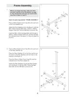
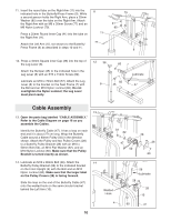
3. Press a 25mm x 50mm Inner Cap (39) into the support tube on the Front Upright (4). Slide the Front Upright (4) onto the M8 x 70mm Carriage Bolts (64) in the Base (1). Thread an M8 Nylon Locknut (70) onto each Carriage Bolt. Do not tighten the Nylon Locknuts yet. 3 Support Tube 39 4 70 70 4. Place the Weight Bumpers (44) over the outer holes in the bracket on the Base (1). Make sure that the flat sides of the Weight Bumpers are facing the floor. Insert the Weight Guides (13) into the holes in the bracket on the Base (1). Make sure that the Weight Guides are turned so the indicated holes are at the top. Slide the nine Weight Plates (36) onto the Weight Guides (13). Make sure that the Weight Plates are turned correctly-the large grooves in the Weight Plates must be facing the floor and the adjustment holes must be on the side shown. Press the Adjustment Tube Cap (43) into the lower end of the Adjustment Tube (14). Insert the Adjustment Tube into the stack of Weight Plates (36). Slide the Top Weight (17) onto the Weight Guides (13). Make sure that the groove in one side of the Top Weight is facing the floor and that it fits over the spring pins on the Adjustment Tube (14). 64 4 Holes 13 Spring Pin Adjustment Holes 44 1 17 14 43 36 1 7
-
 1
1 -
 2
2 -
 3
3 -
 4
4 -
 5
5 -
 6
6 -
 7
7 -
 8
8 -
 9
9 -
 10
10 -
 11
11 -
 12
12 -
13
-
14
-
15
-
16
-
17
-
18
-
19
-
20
-
21
-
22
-
23
-
24
-
25
 |
 |
