Whirlpool KDSS907SSS Installation Instructions - Page 17
Electronic Ignition System - installation guide
 |
View all Whirlpool KDSS907SSS manuals
Add to My Manuals
Save this manual to your list of manuals |
Page 17 highlights
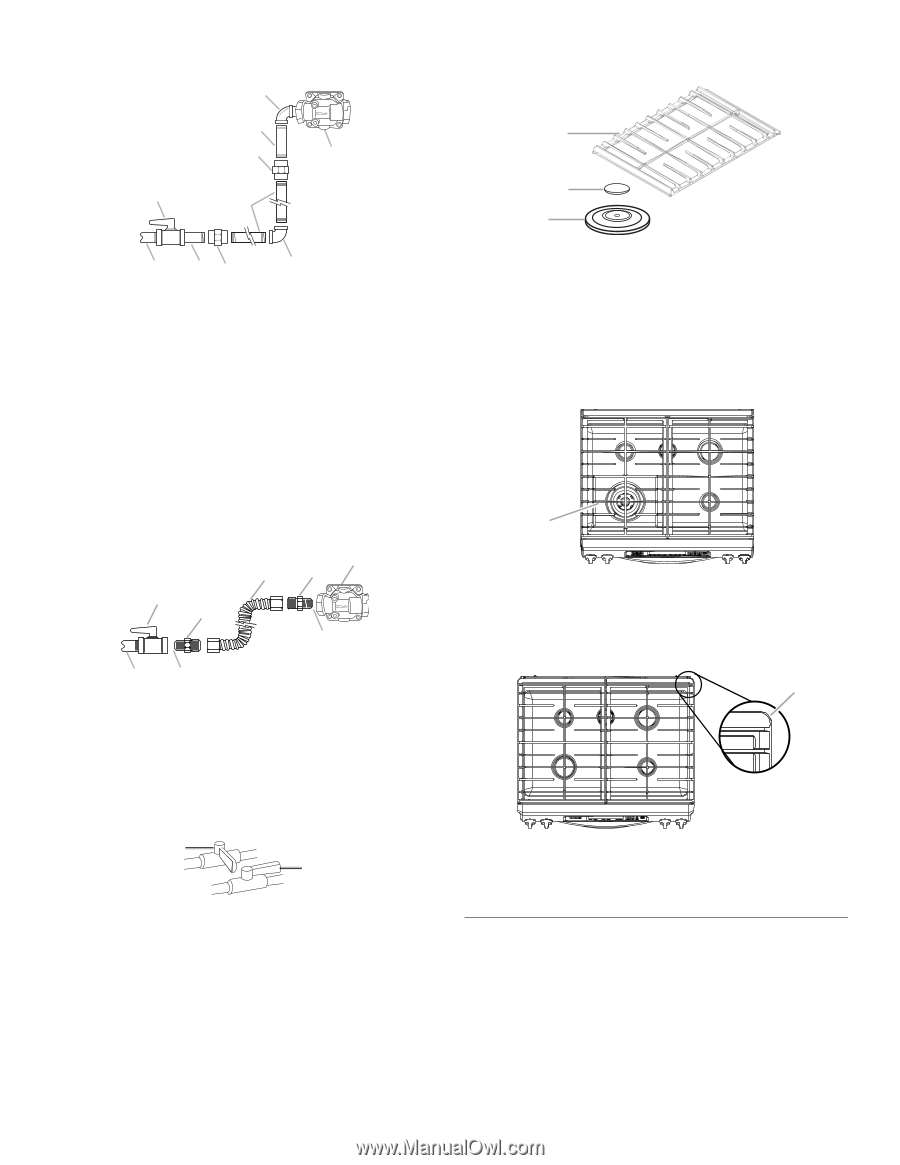
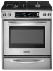
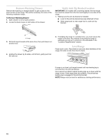
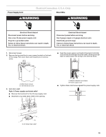
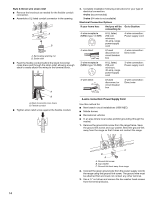
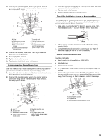
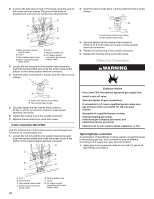
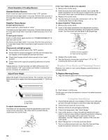
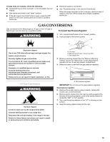
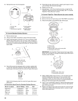
2. Using a pipe wrench to tighten, connect the gas supply to the range. I If burner caps are not properly positioned, surface burners will not light. H C G J B F B A A CD A. ½" or ¾" gas pipe B. Manual gas shutoff valve C. Nipple D. Union E. 90° elbow E F. Black iron pipe G. Union H. Nipple I. 90° elbow (must have ½" male pipe thread) J. Gas pressure regulator Typical flexible connection 1. Apply pipe-joint compound made for use with LP gas to the smaller thread ends of the flexible connector adapters (see C and G in the following illustration). 2. Attach one adapter to the gas pressure regulator and the other adapter to the gas shutoff valve. Tighten both adapters. 3. Use a combination wrench and channel lock pliers to attach the flexible connector to the adapters. Check that connector is not kinked. H E F B D G A C A. ½" or ¾" gas pipe B. Manual gas shutoff valve C. Use pipe-joint compound D. Adapter E. Flexible connector F. Adapter (must have ½" male pipe thread) G. Use pipe-joint compound H. Gas pressure regulator A. Burner base B. Burner cap C. Burner grate 4. Place burner grates over burners and caps as shown in the following illustration. When properly installed the grates should not overlap the console. Freestanding Ranges Opening in grate for wok insert is located over left front burner. A A. Opening in grate for wok insert Slide-In Ranges Large flange with rounded corner must be at the rear corner of the cooktop. A Complete Connection 1. Open the manual shutoff valve in the gas supply line. The valve is open when the handle is parallel to the gas pipe. A B A. Closed valve B. Open valve 2. Test all connections by brushing on an approved noncorrosive leak-detection solution. If bubbles appear, a leak is indicated. Correct any leak found. 3. Remove cooktop burner caps and grates from parts package. Align notches in burner caps with pins in burner base. Burner caps should be level when properly positioned. A. Large flange with rounded corner 5. Plug in range or reconnect power. "Clock-Enter Time" should appear in the display. For further information, please refer to the user instructions located in the Use and Care Guide. Electronic Ignition System Initial lighting and gas flame adjustments Cooktop burners use electronic igniters in place of standing pilots. When the cooktop control knob is turned to the "LITE" position, the system creates a spark to light the burner. This sparking continues, as long as the control knob is turned to "LITE." 17
-
 1
1 -
2
-
3
-
4
-
5
-
6
-
7
-
8
-
9
-
10
-
11
-
 12
12 -
 13
13 -
 14
14 -
 15
15 -
 16
16 -
 17
17 -
 18
18 -
 19
19 -
 20
20 -
 21
21 -
 22
22 -
23
-
24
-
25
-
26
-
27
-
28
-
29
-
30
-
31
-
32
-
33
-
34
-
35
-
36
-
37
-
38
-
39
-
40
 |
 |