Whirlpool KDSS907SSS Installation Instructions - Page 4
Installation Requirements - range
 |
View all Whirlpool KDSS907SSS manuals
Add to My Manuals
Save this manual to your list of manuals |
Page 4 highlights
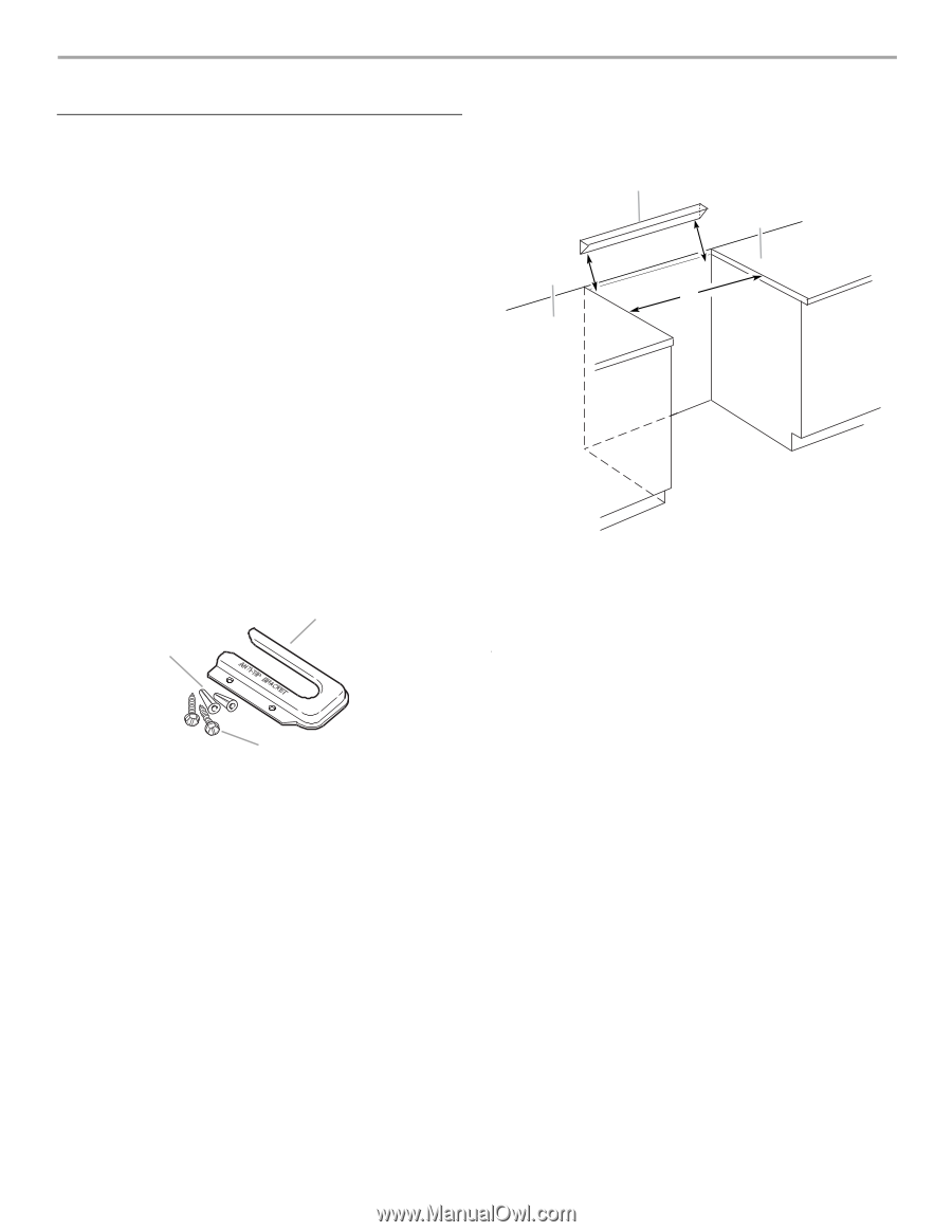
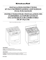
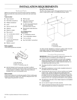
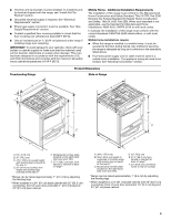
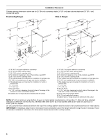
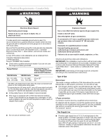
INSTALLATION REQUIREMENTS Tools and Parts Gather the required tools and parts before starting installation. Read and follow the instructions provided with any tools listed here. Tools needed ■ Tape measure ■ Masking tape ■ Flat-blade screwdriver ■ Phillips screwdriver ■ Level ■ Hand or electric drill ■ Pipe-joint compound resistant to LP gas 4.8 mm) carbide-tipped masonry drill bit (for concrete/ceramic floors) Rear Filler Strip (optional) The filler strip may be used to fill a gap between the rear of the slide-in range and the wall in a freestanding range cutout. A B B C ■ Hammer ■ Wrench or pliers ■ Pipe wrench combination wrench nut driver nut driver 3.2 mm) drill bit (for wood floors) ■ Noncorrosive leak-detection solution For LP/Natural Gas Conversions ■ ½" combination wrench ■ 7 mm combination wrench ■ 7 mm nut driver ■ Size T20 TORX®† screwdriver ■ Marker or pencil Parts supplied Check that all parts are included. A B C A. Anti-tip bracket B. Plastic anchors (2) C. #10 x ¹⁄₂" mounting screws (2) ■ Anti-tip bracket must be securely mounted to subfloor. Thickness of flooring may require longer mounting screws to anchor bracket to subfloor. Longer mounting screws are available from your local hardware store. Parts needed Check local codes and consult gas supplier. Check existing gas supply and electrical supply. See "Electrical Requirements" and "Gas Supply Requirements" sections. A. Filler strip B. Countertop C. Countertop cutout To order, see the "Assistance or Service" section of the Use and Care Guide. Order Part Number W10113902A (black), W10113903A (white) or W10113904A (biscuit). Location Requirements IMPORTANT: Observe all governing codes and ordinances. Do not obstruct flow of combustion and ventilation air. ■ It is the installer's responsibility to comply with installation clearances specified on the model/serial rating plate. The model/serial rating plate is located inside the oven door on the right-hand side oven door trim. ■ The range should be located for convenient use in the kitchen. ■ Recessed installations must provide complete enclosure of the sides and rear of the range. ■ To eliminate the risk of burns or fire by reaching over heated surface units, cabinet storage space located above the surface units should be avoided. If cabinet storage is to be provided, the risk can be reduced by installing a range hood or microwave hood combination that projects horizontally a minimum of 5" (12.7 cm) beyond the bottom of the cabinets. ■ All openings in the wall or floor where range is to be installed must be sealed. ■ Do not seal the range to the side cabinets. ■ Cabinet opening dimensions that are shown must be used. Given dimensions are minimum clearances. †®TORX is a registered trademark of Textron Innovations Inc. 4
-
 1
1 -
 2
2 -
 3
3 -
 4
4 -
 5
5 -
 6
6 -
 7
7 -
 8
8 -
 9
9 -
 10
10 -
11
-
12
-
13
-
14
-
15
-
16
-
17
-
18
-
19
-
20
-
21
-
22
-
23
-
24
-
25
-
26
-
27
-
28
-
29
-
30
-
31
-
32
-
33
-
34
-
35
-
36
-
37
-
38
-
39
-
40
 |
 |