Whirlpool WEG730H0DS Installation Guide - Page 12
Verify Anti-Tip Bracket Is Installed and, Engaged
 |
View all Whirlpool WEG730H0DS manuals
Add to My Manuals
Save this manual to your list of manuals |
Page 12 highlights
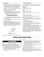
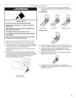
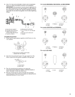
5. Align the gas tube opening in the burner base with the orifice holder on the cooktop and the igniter electrode with the notch in the burner base. A WARNING B C E D A. Burner cap B. Gas tube opening C. Burner base D. Igniter electrode E. Orifice holder 6. Place the burner caps on the appropriate burner bases. IMPORTANT: The bottom of the small and medium caps are different. Do not put the wrong size burner cap on the burner base. Small cap Medium cap Large cap X-Large cap Burner caps should be level when properly positioned. If burner caps are not properly positioned, surface burners will not light. The burner cap should not rock or wobble when properly aligned. A B A. Incorrect B. Correct Electrical Shock Hazard Plug into a grounded 3 prong outlet. Do not remove ground prong. Do not use an adapter. Do not use an extension cord. Failure to follow these instructions can result in death, fire, or electrical shock. 7. Plug into a grounded 3 prong outlet. Verify Anti-Tip Bracket Is Installed and Engaged On Ranges Equipped with a Premium Storage Drawer: 1. Slide range into final location, making sure rear leveling leg slides into anti-tip bracket. 2. Remove the premium storage drawer. See the "Remove/ Replace Drawer" section. 3. Use a flashlight to look underneath the bottom of the range. 4. Visually check that the rear range foot is inserted into the slot of the anti-tip bracket. On Ranges Equipped with a Warming Drawer or Baking Drawer: 1. Slide range into final location, making sure rear leveling leg slides into anti-tip bracket. Leave a 1" (2.5 cm) gap between the back of the range and the back wall. 2. Place the outside of your foot against the bottom front of the warming drawer or baking drawer to keep the range from moving, and grasp the back of the range as shown. 3. Slowly attempt to tilt the range forward. If you encounter immediate resistance, the range foot is engaged in the anti-tip bracket. Go to Step 8. 12
-
 1
1 -
2
-
3
-
4
-
5
-
6
-
 7
7 -
 8
8 -
 9
9 -
 10
10 -
 11
11 -
 12
12 -
 13
13 -
 14
14 -
 15
15 -
 16
16 -
 17
17 -
18
-
19
-
20
-
21
-
22
-
23
-
24
-
25
-
26
-
27
-
28
-
29
-
30
-
31
-
32
-
33
-
34
-
35
-
36
-
37
-
38
-
39
-
40
-
41
-
42
-
43
-
44
-
45
-
46
-
47
-
48
 |
 |
