Yamaha DVD-CX1 Owners Manual - Page 13
Video connections, PREPARATION, Component Video terminal 1
 |
View all Yamaha DVD-CX1 manuals
Add to My Manuals
Save this manual to your list of manuals |
Page 13 highlights
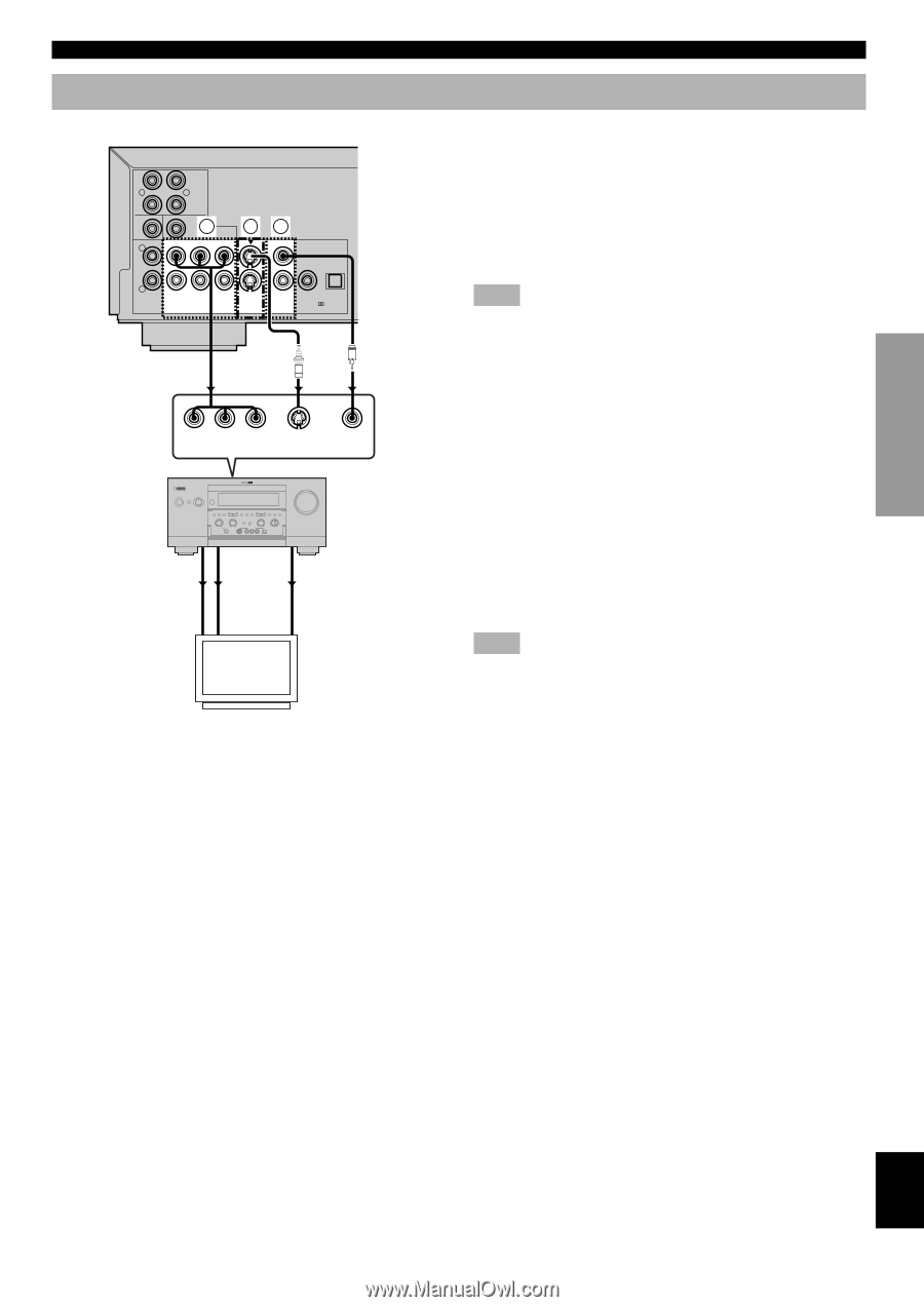
INTRODUCTIOIN PREPARATION Video connections (U.S.A. model) R CENTER L MAIN L SORROUND A SUB WOOFER 6CH BC DISCRETE 1 1 R 2 MIXED 2CH Y PB PR AUDIO OUT COMPONENT VIDEO OUT (480p/480i) 2 S VIDEO VIDEO VIDEO OUT COAXIAL PCM/ DTS OPTICAL DIGITAL V S Y PBCB PRCR COMPONENT S VIDEO VIDEO VIDEO IN INPUT STANDBY /ON INPUT SELECTOR INPUT MODE SPEAKERS A B 6CH INPUT BASS PROGRAM TREBLE SILENT STEREO FM/AM A/B/C/D/E PRESET /TUNING PRESET TUNING /TUNING MEMORY MODE EFFECT PROCESSOR BASS DIRECT EXTENSION ON OFF VIDEO AUX BALANCE L R EDIT MAN'L/AUTO FM AUTO/MAN'L MONO SOURCE/REMOTE D-TV/LD DVD CABLE MD/TAPE SAT CD-R VCR 1 TUNER VCR 2 CD VCR 3/DVR PHONO VIDEO AUX REC OUT/ZONE 2 PHONES S VIDEO VIDEO L AUDIO R OPTICAL VOLUME AV amplifier COMPONENT VIDEO OUT S VIDEO OUT VIDEO OUT COMPONENT VIDEO IN S VIDEO IN VIDEO IN Video monitor CONNECTIONS If your AV amplifier has video terminals, connect your amplifier (and then to your video monitor) so that you can use one video monitor for several different video sources (LD, VCR etc.) by simply switching the input source selector of your amplifier. This unit has three types of video output terminals. Use one of them in accordance with the input terminals of the equipment to be connected. Note • Do not connect this unit to a video monitor through a video cassette recorder. If you do so, the picture may not be played back properly due to the copyright protection technology incorporated in this unit. A Component Video terminal (1, 2) Component video connection achieves high fidelity in reproducing colors (better performance than S-video connection), separating video signal into luminance (Y, terminal color-coded as green), and color difference (PB, blue/PR, red). Use commercially available coaxial cables. Amplifier (and Video monitor) with component input is required. Observe the color of each terminal when connecting. If your amplifier does not have component output terminals, connecting this unit's component output directly to your video monitor's component input can reproduce better video image. Note • Do not connect this unit's COMPONENT VIDEO OUT terminals to component video input terminals special for HD (HighDefinition) TV. BS-Video terminal (1, 2) S (separate) video connection achieves a clearer picture than composite video connection by separating color and luminance when transmitting signals. Use commercially available S-video cable. Amplifier (and Video monitor) with S-video input is required. C Composite Video terminal (1, 2) Use RCA video cable supplied with this unit when connecting this unit to a video monitor. VIDEO 1, 2 terminals of VIDEO OUT output the same signal. You can connect one to your amplifier's input using supplied RCA cable, and the other to another amplifier or a video monitor. PLAYBACK SETUP MENU APPENDIX English 9
-
 1
1 -
2
-
3
-
4
-
5
-
6
-
7
-
 8
8 -
 9
9 -
 10
10 -
 11
11 -
 12
12 -
 13
13 -
 14
14 -
 15
15 -
 16
16 -
 17
17 -
 18
18 -
19
-
20
-
21
-
22
-
23
-
24
-
25
-
26
-
27
-
28
-
29
-
30
-
31
-
32
-
33
-
34
-
35
-
36
 |
 |