Yamaha MM1242 Owner's Manual - Page 6
PAN control, PEAK indicator, PFL switch, Fader, from a particular channel
 |
View all Yamaha MM1242 manuals
Add to My Manuals
Save this manual to your list of manuals |
Page 6 highlights
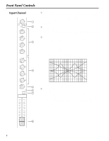
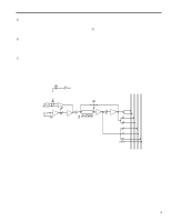
5 PAN control The PAN control determines the position in the stereo sound field at which the sound from that channel is heard, by distributing signal from each channel to STEREO L and R buses. 6 PEAK indicator The PEAK indicator LED lights in red when the pre-EQ, post-EQ, or post-fader signal of the corresponding channel's input reaches a level 3dB below the clipping level. 7 PFL switch Press this switch to monitor the pre-fader input channel signal through the MONITOR OUT or the PHONES connector. This is useful when you wish to monitor only the signal from a particular channel, or take a countermeasure for a problem. 8 Fader This is the main level control for each input channel. It determines the level of the signal sent from the corresponding input channel to the master stereo bus. The settings of the input channel faders determine the "mix" or balance of sound levels between the instruments or other sources connected to the inputs. Lower the faders of unused channels to the bottom. PFL CTRL AUX STEREO PFL 4 2 3 1 L R MIC IN 1-12 PHANTOM OFF (MIC IN) ON PHANTOM (+48V) (PHANTOM) HA LINE IN 1-12 HA GAIN BA LINE MIC PEAK EQ BA LOW LO-MID HI-MID HIGH BA PAN AUX 1 AUX 2 AUX 3 AUX 4 (+V) PFL 3
-
 1
1 -
 2
2 -
 3
3 -
 4
4 -
 5
5 -
 6
6 -
 7
7 -
 8
8 -
 9
9 -
 10
10 -
 11
11 -
 12
12 -
13
-
14
-
15
-
16
-
17
-
18
-
19
-
20
-
21
-
22
-
23
-
24
-
25
-
26
-
27
-
28
-
29
-
30
-
31
-
32
-
33
-
34
-
35
-
36
-
37
-
38
-
39
-
40
-
41
-
42
-
43
-
44
-
45
-
46
-
47
-
48
-
49
-
50
 |
 |
