Yamaha MM1242 Owner's Manual - Page 9
Rear Panel, MIC IN connectors, LINE IN, AUX send jacks, ST AUX RTN jacks, STEREO OUT, MONITOR OUT
 |
View all Yamaha MM1242 manuals
Add to My Manuals
Save this manual to your list of manuals |
Page 9 highlights
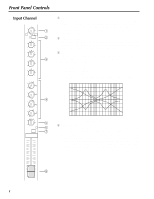
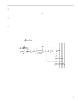
s Rear Panel 7 3 AUX SEND +4dB MIC IN 4 3 2 1 12 11 10 9 8 7 6 5 4 3 2 1 ON OFF 4 3 2 1 PHANTOM L ST AUX RTN -10dB 12 11 10 9 8 7 6 5 4 3 2 1 LINE IN R MONITOR OUT +4dB R L STEREO OUT +4dB 6 54 1 2 1 MIC IN connectors These are XLR-type connectors to connect microphones. (Pin assignment - 1: GND, 2: hot, 3: cold) Impedance range is 50Ω to 600Ω. Turn the PHANTOM switch ON to apply +48V DC to Pin 2 and 3 of these connectors. 2 LINE IN These are unbalanced phone jacks used to connect line sources. (Impedance: 600Ω) 3 AUX send jacks These are unbalanced phone jacks. (T: hot, R: cold, S: GND) Nominal output level and impedance is +4dB/600Ω. 4 ST AUX RTN jacks These are stereo type phone jacks. Nominal output level and impedance is -10dB/600Ω. Usually, the output from effects units such as delay and reverb are returned to the main stereo mix via these jacks. However, you can use these as auxiliary inputs. 5 STEREO OUT These are XLR type connectors used to connect a power amplifier. (Pin assignment - 1: GND, 2: hot, 3: cold) MICROPHONE CABLES AND MICROPHONES CONNECTION TO PREVENT HAZARD OR DAMAGE, ENSURE THAT ONLY MICROPHONE CABLES AND MICROPHONES DESIGNED TO THE IEC268-15A STANDARD ARE CONNECTED. 6 6 MONITOR OUT These are unbalanced phone jacks used to connect monitor speakers. You can monitor the following signals: - Signals available for monitoring - 1. Post-EQ signal (when the corresponding channel PFL switch is ON) 2. Pre-fader ST signal (when the corresponding stereo L/R PFL switch is ON) 3. Pre-AUX SEND 3/4-fader signal (when the corresponding AUX send 3/4 PFL switch is ON) 7 PHANTOM switch This switch is used to turn on/off all channels' phantom power simultaneously. Set this switch to ON when using condenser microphones to apply +48V DC to Pin 2 and 3 of all the MIC IN connectors 1-12. Be sure to turn this switch OFF when the phantom power is not in use. * You may connect balanced dynamic microphones or line sources when this switch is ON. However, connecting, unbalanced devices, or devices in which the center of the transformer is grounded may cause hum noise or malfunction. The phantom power supply can provide a maximum of 40 mA of current. Check the specifications of your condenser mics, and make sure that the total current consumption is no more than 40 mA.
-
 1
1 -
2
-
3
-
 4
4 -
 5
5 -
 6
6 -
 7
7 -
 8
8 -
 9
9 -
 10
10 -
 11
11 -
 12
12 -
 13
13 -
 14
14 -
15
-
16
-
17
-
18
-
19
-
20
-
21
-
22
-
23
-
24
-
25
-
26
-
27
-
28
-
29
-
30
-
31
-
32
-
33
-
34
-
35
-
36
-
37
-
38
-
39
-
40
-
41
-
42
-
43
-
44
-
45
-
46
-
47
-
48
-
49
-
50
 |
 |
