Yamaha YPP-200 Owner's Manual - Page 46
Keyboard Stand Assembly, Assembly Parts
 |
View all Yamaha YPP-200 manuals
Add to My Manuals
Save this manual to your list of manuals |
Page 46 highlights
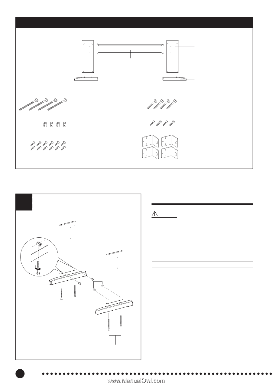
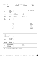
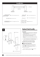
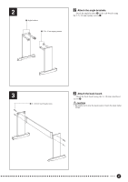
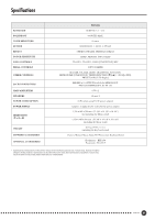
Assembly Parts Back board 1 6 x 70 mm round head screws (4 pcs.) 2 Joint connectors (4 pcs.) 3 3.5 x 16 mm tapping screws (12 pcs.) Side boards Stand bases 4 6 x 30 mm round head screws (4 pcs.) 5 5 x 16 mm round head screws (4 pcs.) 6 Angle brackets (4 pcs.) 1 Keyboard Stand Assembly 2 Joint connectors CAUTION • Be careful not to confuse parts, and be sure to install all parts in the correct direction. Please assemble in accordance with the sequence given below. • Assembly should be carried out by at least two persons. • Be sure to use the correct screw size, as indicated above. Use of incorrect screws can cause damage. • Be sure to tighten up all screws upon completing assembly of each unit. • To disassemble, reverse the assembly sequence given below. Have a Phillips-head (+) screwdriver ready. The parts shown in the "Assembly Parts" illustration will be used. Follow the assembly instructions and select the parts as needed. Z Attach the stand bases. Making sure that the boards are facing the proper direction (the holes should face inside), insert the joint connectors 2 into the holes as shown. The joint connectors have been installed properly if you can see a plus mark on the connector. Attach the stand bases to the rear of the side boards, using the 6 x 70 mm round head screws 1. 1 6 x 70 mm round head screws 46 YPP-200
-
 1
1 -
2
-
3
-
4
-
5
-
6
-
7
-
8
-
9
-
10
-
11
-
12
-
13
-
14
-
15
-
16
-
17
-
18
-
19
-
20
-
21
-
22
-
23
-
24
-
25
-
26
-
27
-
28
-
29
-
30
-
31
-
32
-
33
-
34
-
35
-
36
-
37
-
38
-
39
-
40
-
 41
41 -
 42
42 -
 43
43 -
 44
44 -
 45
45 -
 46
46 -
 47
47 -
 48
48 -
 49
49 -
 50
50 -
 51
51 -
52
 |
 |