3Ware CBL-P-SATA Installation Guide - Page 14
Installing a Serial ATA RAID Controller - sata raid
 |
View all 3Ware CBL-P-SATA manuals
Add to My Manuals
Save this manual to your list of manuals |
Page 14 highlights
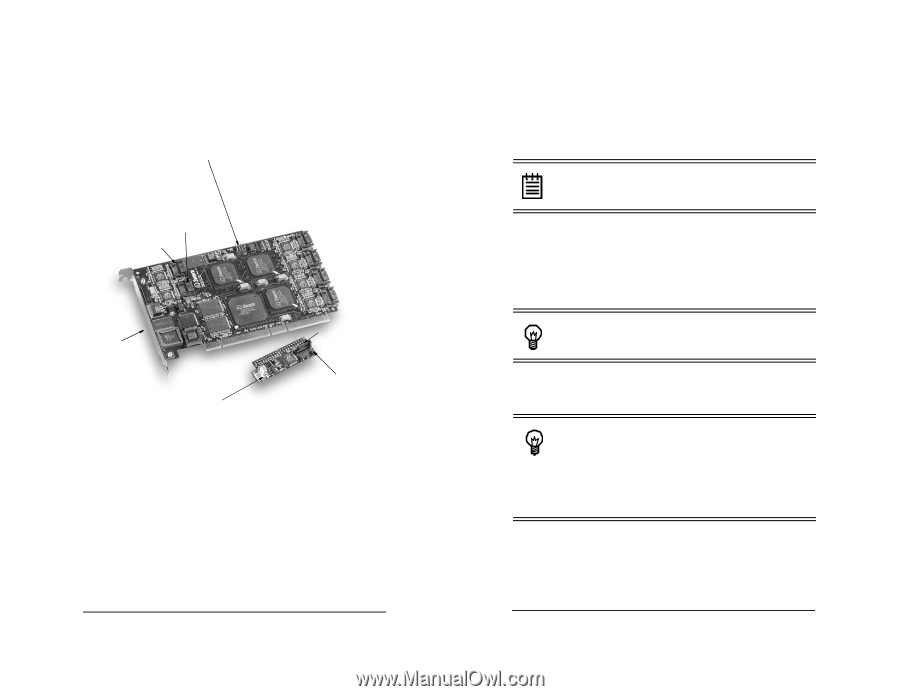
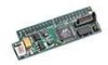
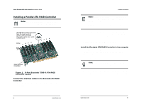
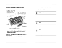
3ware Escalade ATA RAID Controller Installation Guide Installing a Serial ATA RAID Controller JP2 LED drive status connector Note: Pin 1 and 4 are 3.3V and pin 2 and 3 are ground Plug cable to either pins 1 and 2 or pins 3 and 4. Ports 8 and 9 Ports 10 and 11 Ports not shown: 1, 3, 5, and 7, located on the under side of ports 0 through 6 9 and 11, located on the under side of ports 8 and 10 Ports: 6 and 7 4 and 5 2 and 3 0 and 1 Serial Number (on plate) Power Converter Adapter Connector Serial ATA Cable Connector Jumper Settings Figure 2. 12-Port Escalade 8500-12 Serial ATA RAID Controller with CBL-P-SATA (Parallel to Serial ATA Converter) Connect the interface cables to the Escalade Serial ATA RAID Controller 1 Connect the interface cables supplied with the product to the ATA RAID Controller. See Figure 2. 18 www.3ware.com Hardware Installation 2 One edge of each interface cable connector is keyed to ensure proper orientation and installation. Carefully mate the connectors without bending any pins. 3 Install the other connectors in the same manner. Note: The connectors on the end of the controller are susceptible to damage from excessive bending. 1 If the computer is running, shut it down. Turn off power to the computer and disconnect the power cord from the outlet. 2 Open the computer case according to the manufacturer's instrutions. 3 Find the PCI slot you want to use for the serial ATA RAID Controller. Hint: Cable routing may be easier if you install the ATA RAID Controller next to an open slot. 4 Remove the metal filler bracket for the slot. Save this screw; it will be used to secure the serial ATA RAID Controller after you have seated it in the slot. Hint: While the ATA RAID Controller runs properly in any PCI slot, not all slots give equal performance due to the architecture of the PCI bus. In our laboratories, we have noticed that the slots closest to the Accelerated Graphics Port (AGP) or in the 64-bit PCI slot typically give the best performance. Our card should fit in both 32-bit and 64-bit PCI slots with 5V as well as with 3.3V. 5 Line up the ATA RAID Controller so that all pins make proper contact with the PCI slot pins when pushed into place. The www.3ware.com 19
-
 1
1 -
2
-
3
-
4
-
5
-
6
-
7
-
8
-
 9
9 -
 10
10 -
 11
11 -
 12
12 -
 13
13 -
 14
14 -
 15
15 -
 16
16 -
 17
17 -
 18
18 -
 19
19 -
20
-
21
-
22
-
23
-
24
-
25
-
26
-
27
-
28
-
29
-
30
-
31
-
32
-
33
-
34
-
35
-
36
-
37
-
38
-
39
 |
 |