3Ware CBL-P-SATA Installation Guide - Page 9
Tools Required, System Requirements, Personal Safety, Protecting Equipment and Data, ESD Precautions - card
 |
View all 3Ware CBL-P-SATA manuals
Add to My Manuals
Save this manual to your list of manuals |
Page 9 highlights
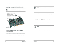
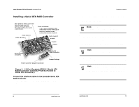
3ware Escalade ATA RAID Controller Installation Guide CBL-P-SATA (Parallel to Serial Drive Converter Kit) • Escalade CBL-P-SATA (one per port) • Power Converter Adapter (one per port) • Jumper(s) for converter (if not already installed) • 3ware Installation Guide Tools Required • An ESD grounding strap or mat • Standard hand tools to open your system's case and install the Escalade ATA RAID Controller into an available PCI expansion slot. System Requirements The Escalade ATA RAID Controller requires a workstation-class or server-class CPU whose bus complies with PCI 2.2 standards, and a PCI slot that meets the Plug and Play and PC99 specifications. The ATA RAID Controller may be connected to up to two, four, eight, or twelve IDE/ATA drives by the supplied interface cables. Note: It is recommended that the Escalade 7000 or 8000 card be installed in the 64-bit PCI slot whenever possible for the best performance. The controllers fit in both 32-bit and 64-bit PCI slots with 5V as well as 3.3V. The 12-port 7000 board requires one full size PCI slot. . Drives must meet UltraATA-133, UltraATA-100, UltraATA-66 or UltraATA-33 standards (8000 family does not support UltraDMA66 or UltraDMA-33 standards), but may be of any capacity or physical form factor. Length of unshielded interface cables may not 10 www.3ware.com Before you Begin exceed 36" (91.4 cm) for parallel ATA controllers and 1M (39") for serial ATA controllers. Personal Safety Warning! High voltages may be found inside computer equipment. Before installing any of the hardware in this package or removing the protective covers of any computer equipment, turn off power switches and disconnect power cords. Do not reconnect the power cords until you have replaced the covers. Protecting Equipment and Data Back up your data! Creating or deleting disk arrays destroys existing files on the member drives. If your drives contain valuable data, back them up and save data elsewhere before changing your array configuration. ESD Precautions Standard electrostatic discharge (ESD) precautions must be followed to avoid damaging computer components and accessories when installing or removing the EscaladeATA RAID Controller. • When the case of your computer is open and its internal parts are exposed, don't touch any internal part unnecessarily. • Always wear a grounded strap or work on an ESD-protective mat. • Don't remove the ATA RAID Controller from its protective bag until you are properly grounded. www.3ware.com 11
-
 1
1 -
2
-
3
-
 4
4 -
 5
5 -
 6
6 -
 7
7 -
 8
8 -
 9
9 -
 10
10 -
 11
11 -
 12
12 -
 13
13 -
 14
14 -
15
-
16
-
17
-
18
-
19
-
20
-
21
-
22
-
23
-
24
-
25
-
26
-
27
-
28
-
29
-
30
-
31
-
32
-
33
-
34
-
35
-
36
-
37
-
38
-
39
 |
 |