ASRock 4Core1333-Viiv User Manual - Page 23
PCIE1 port, yellow, PCIE2 port, white, Hot Plug detection header, JHP1; black, ASRock PCIE_DE card,
 |
View all ASRock 4Core1333-Viiv manuals
Add to My Manuals
Save this manual to your list of manuals |
Page 23 highlights
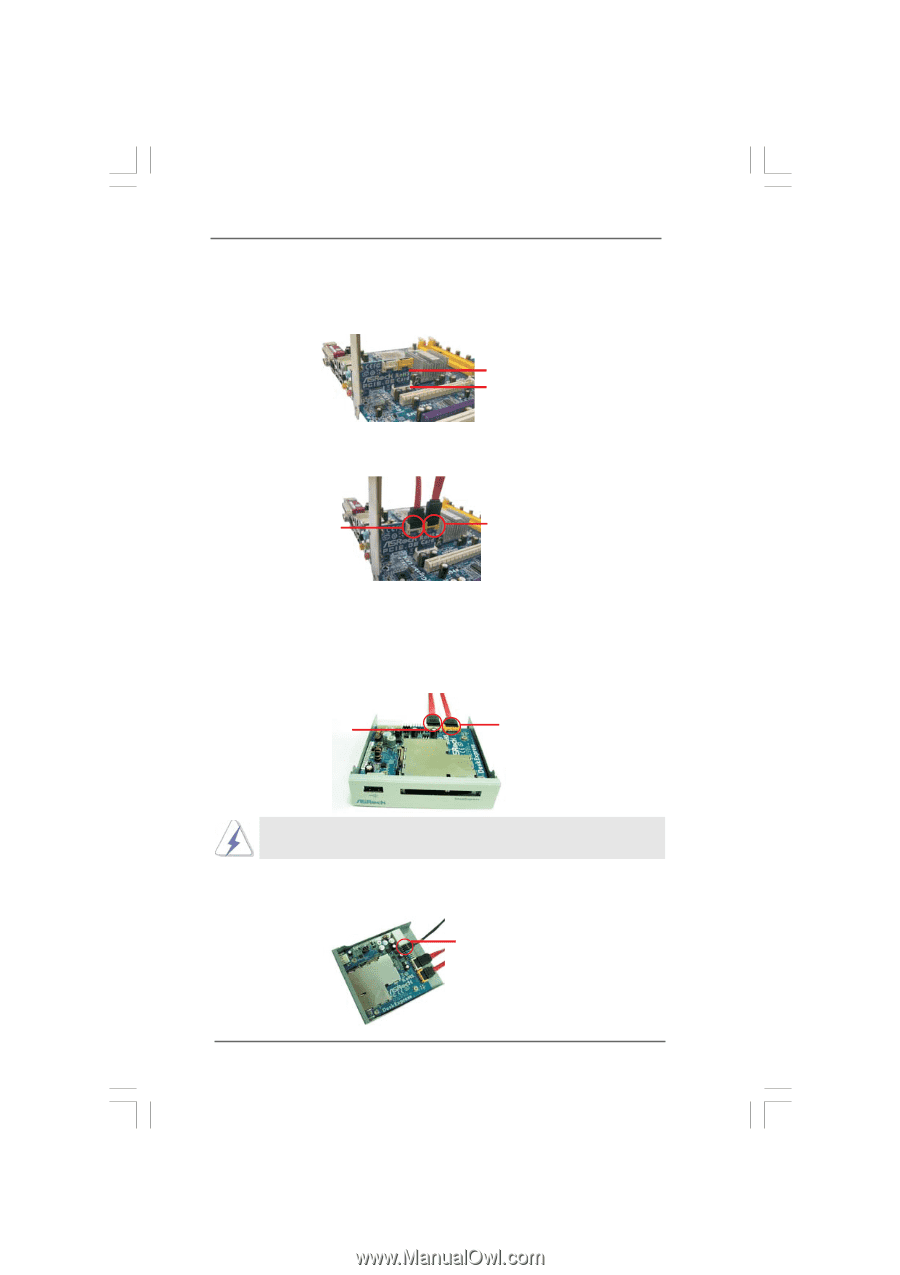
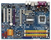
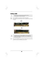
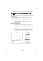
Step 1. Install ASRock PCIE_DE card to PCIE1 slot on this motherboard. For the proper installation of ASRock PCIE_DE card, please refer to the installation guide on page 20. ASRock PCIE_DE card PCIE1 slot Step 2. Connect either end of SATA data cable to PCIE1 (yellow) / PCIE2 (white) port on ASRock PCIE_DE card. PCIE2 port (white) PCIE1 port (yellow) Step 3. Connect the other end of SATA data cable to PCIE1 (yellow) / PCIE2 (white) port on ASRock DeskExpress. Please correctly connect the SATA data cables to the ports with corresponding colors on ASRock PCIE_DE card and ASRock DeskExpress. (PCIE1 (yellow) port to PCIE1 (yellow) port; PCIE2 (white) port to PCIE2 (white) port.) PCIE2 port (white) PCIE1 port (yellow) If you do not connect SATA data cable to the correct port, ASRock PCIE_DE card and ASRock DeskExpress will not function. Step 4. Connect either end of DeskExpress Hot Plug detection cable to Hot Plug detection header (JHP1; black) on ASRock DeskExpress. Hot Plug detection header (JHP1; black) 23
-
 1
1 -
2
-
3
-
4
-
5
-
6
-
7
-
8
-
9
-
10
-
11
-
12
-
13
-
14
-
15
-
16
-
17
-
 18
18 -
 19
19 -
 20
20 -
 21
21 -
 22
22 -
 23
23 -
 24
24 -
 25
25 -
 26
26 -
 27
27 -
 28
28 -
29
-
30
-
31
-
32
-
33
-
34
-
35
-
36
-
37
-
38
-
39
-
40
-
41
-
42
-
43
-
44
-
45
-
46
-
47
-
48
-
49
-
50
-
51
-
52
-
53
-
54
-
55
-
56
-
57
-
58
-
59
-
60
-
61
-
62
-
63
-
64
-
65
-
66
-
67
-
68
 |
 |