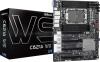
ASRock C621A WS User Manual
ASRock C621A WS Manual
 |
View all ASRock C621A WS manuals
Add to My Manuals
Save this manual to your list of manuals |
ASRock C621A WS manual content summary:
- ASRock C621A WS | User Manual - Page 1
- ASRock C621A WS | User Manual - Page 2
documentation are furnished for informational use only and subject to change without notice, and should not be constructed as a commitment by ASRock. ASRock assumes no responsibility for any errors or omissions that may appear in this documentation. With respect to the contents of this documentation - ASRock C621A WS | User Manual - Page 3
replaced if the goods fail to be of acceptable quality and the failure does not amount to a major failure. If you require assistance please call ASRock Tel : +886-2-28965588 ext.123 (Standard International call charges apply) - ASRock C621A WS | User Manual - Page 4
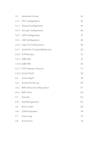
Jumper Setup 25 2.7 Onboard Headers and Connectors 27 2.8 Unit Identification purpose LED/Switch 35 2.9 Driver Installation Guide 35 2.10 M.2_SSD (NGFF) Module Installation Guide 36 Chapter 3 UEFI Setup Utility 38 3.1 Introduction 38 3.1.1 UEFI Menu Bar 38 3.1.2 Navigation Keys 39 - ASRock C621A WS | User Manual - Page 5
3.3 Advanced Screen 41 3.3.1 CPU Configuration 42 3.3.2 Chipset Configuration 43 3.3.3 Storage Configuration 46 3.3.4 ACPI Configuration 47 3.3.5 USB Configuration 48 3.3.6 Super IO Configuration 49 3.3.7 Serial Port Console Redirection 50 3.3.8 H/W Monitor 53 3.3.9 AMD CBS 55 - ASRock C621A WS | User Manual - Page 6
Chapter 4 Software Support 75 4.1 Install Operating System 75 4.2 Support CD Information 75 4.2.1 Running The Support CD 75 4.2.2 Drivers Menu 75 4.2.3 Utilities Menu 75 Chapter 5 Troubleshooting 76 5.1 Troubleshooting Procedures 76 - ASRock C621A WS | User Manual - Page 7
may find the latest VGA cards and CPU support list on ASRock's website as well. ASRock website http://www.asrock.com. 1.1 Package Contents • ASRock C621A WS Motherboard (ATX Form Factor) • ASRock C621A WS Quick Installation Guide • ASRock C621A WS Support CD • 1 x CPU Non-Fabric Carrier (Optional - ASRock C621A WS | User Manual - Page 8
Xeon® Scalable Processors • Intel® Socket 4189 (Socket P+) • Digi Power Design • 7 Power Phase Design Chipset • Intel® C621A Memory • Eight Channel Memory Technology (1DPC) • 8 x DDR4 DIMM Slots • Supports DDR4 3200/2933/2666/2400/2133/1866 DDR4 RDIMM/ RDIMM-3DS/ LRDIMM/ LRDIMM-3DS/ Intel®Optane - ASRock C621A WS | User Manual - Page 9
C621A WS 2 x Gigabit LAN 10/100/1000 Mb/s (Intel® I210) • Supports Wake-On-LAN • Supports Lightning/ESD Protection • Supports Energy Efficient Ethernet 802.3az • Supports PXE 1 x Dedicated IPMI (ASPEED AST2500) • Supports iKVM and vMedia Storage • 2 x SATA3 6.0 Gb/s Connectors • 1 x Mini-SAS HD - ASRock C621A WS | User Manual - Page 10
Interrupt Button Header • 1 x Buzzer • 1 x Dr. Debug with LED BIOS Feature • AMI UEFI Legal BIOS • ACPI 5.0 Compliant wake up events • SMBIOS 2.3 Support English Hardware Monitor • Temperature Sensing: CPU, PCH, MB, Card Side • Fan Tachometer: CPU, Rear, Front Fan Tachometer • Quiet Fan (Auto - ASRock C621A WS | User Manual - Page 11
) system, Intel Raid mode only supports UEFI BOOT. * Ubuntu 18.04 (64bit) does not support Intel Raid mode (AHCI only). • FCC, CE • ErP/EuP ready (ErP/EuP ready power supply is required) * For detailed product information, please visit our website: http://www.asrock.com Please realize that there is - ASRock C621A WS | User Manual - Page 12
FAN4 SATA_5 DDR4_G1 DDR4_H1 SATA_4 DDR4_E1 DDR4_F1 FAN5 BAT1 M2_1 SATA_0_3 USB31_TC_2 USB31_TC_1 SSATA_2_3 PCIE5 PCIE4 C621A WS PCIE3 M2_2 BMC ROM1 PCIE2 PCIE1 NMI_BTN2 COM1 PECI1 ME_RECOVERY1 PASSWORD_CLEAR ESPI_LPC_SEL1 SEC_OR1 BIOS_RECOVERY ESPI_SHARE ESPI_MODE1 MINISAS_1 - ASRock C621A WS | User Manual - Page 13
Panel Header (PANEL1) 30 Auxiliary Panel Header (AUX_PANEL1) 31 M.2 Socket (M2_2) (Type 2242/2280/22110) 32 TPM-SPI Header (TPM_BIOS_PH1) 33 Security Override Jumper (SEC_OR1) C621A WS 7 English - ASRock C621A WS | User Manual - Page 14
2 x 288-pin DDR4 DIMM Slots (DDR4_A1, DDR4_C1)* 61 2 x 288-pin DDR4 DIMM Slots (DDR4_B1, DDR4_D1)* *For DIMM installation and configuration instructions, please see p.21 (Installation of Memory Modules (DIMM)) for more details. **2 Type-C USB headers (USB31_TC1/USB31_TC2) are shared with 2 SATA - ASRock C621A WS | User Manual - Page 15
1.4 Onboard LED Indicators C621A WS 1 2 3 4 5 6 7 English 9 - ASRock C621A WS | User Manual - Page 16
No. Item 1 SB_PWR1 2 FAN_LED1 3 FAN_LED2 4 FAN_LED3 5 FAN_LED4 6 FAN_LED5 7 BLED1 Status Green Amber Amber Amber Amber Amber Green Description STB PWR ready FAN1 failed FAN2 failed FAN3 failed FAN4 failed FAN5 failed BMC heartbeat LED English 10 - ASRock C621A WS | User Manual - Page 17
1.5 I/O Panel 3 5 C621A WS 1 2 4 6 7 8 9 No. Description 1 VGA Port (VGA1) 2 USB 3.2 Gen1 Ports (USB3_3_4) 3 LAN RJ-45 Port (IPMI_LAN)* 4 USB 3.2 Gen1 Ports (USB3_1_2) 5 1G LAN RJ-45 Port (LAN3)** No. - ASRock C621A WS | User Manual - Page 18
*There are two LED next to the LAN port. Please refer to the table below for the LAN port LED indications. ACT/LINK LED SPEED LED LAN Port Dedicated IPMI LAN Port LED Indications Activity / Link LED Speed LED Status Description Status Off No Link Off Blinking Orange Data Activity On - ASRock C621A WS | User Manual - Page 19
C621A WS ***There are two LEDs on each LAN port. Please refer to the table below for the LAN port LED indications. ACT/LINK LED SPEED LED - ASRock C621A WS | User Manual - Page 20
Chapter 2 Installation This is an ATX form factor (12" x 9.6", 30.5 cm x 24.4 cm) motherboard. Before you install the motherboard, study the configuration of your chassis to ensure that the motherboard fits into it. Make sure to unplug the power cord before installing or removing the motherboard. - ASRock C621A WS | User Manual - Page 21
C621A WS 2.3 Installing the CPU and Heatsink 1. Before you insert the CPU into the socket, please check if the PnP cap is on the socket, if the - ASRock C621A WS | User Manual - Page 22
1. Before you installed the heatsink, you need to spray thermal interface material between the CPU and the heatsink to improve heat dissipation. 2. Illustration in this documentation are examples only. Heatsink or fan cooler type may differ. 2 CPU Carrier 3 16 English - ASRock C621A WS | User Manual - Page 23
C621A WS 4 5 180o 17 English - ASRock C621A WS | User Manual - Page 24
6 7 18 CPU Carrier English - ASRock C621A WS | User Manual - Page 25
C621A WS 8 Heatsink CPU Carrier Socket 19 English - ASRock C621A WS | User Manual - Page 26
9 10 20 English - ASRock C621A WS | User Manual - Page 27
C621A WS 2.4 Installation of Memory Modules (DIMM) This motherboard provides eight 288-pin DDR4 (Double Data Rate 4) DIMM slots in two groups, and supports Eight Channel Memory Technology. CPU1 A1 B1 C1 D1 E1 F1 G1 H1 1 DIMM # 2 DIMMS # # 4 DIMMS # # # # 8 DIMMS # # # # # # - ASRock C621A WS | User Manual - Page 28
1 2 3 22 English - ASRock C621A WS | User Manual - Page 29
C621A WS 2.5 Expansion Slots (PCIe Slots) There are 7 PCIe slots on this motherboard. PCIE slot: PCIE1, PCIE3, PCIE5 and PCIE7 (PCIE 4.0 x16 slot, from CPU1) are used - ASRock C621A WS | User Manual - Page 30
Installing an expansion card Step 1. Step 2. Step 3. Step 4. Step 5. Before installing an expansion card, please make sure that the power supply is switched off or the power cord is unplugged. Please read the documentation of the expansion card and make necessary hardware settings for the card - ASRock C621A WS | User Manual - Page 31
C621A WS 2.6 Jumper Setup The illustration shows how jumpers are setup. When the jumper cap is placed on the pins, the jumper is "Short". If no jumper - ASRock C621A WS | User Manual - Page 32
BIOS Recovery Jumper (3-pin BIOS_RECOVERY1) (see p.6, No. 45) Normal Mode (Default) Recover BIOS ESPI/LPC Selection Jumper (3-pin ESPI_LPC_SEL1) (see p.6, No. 54) ESPI (Default) LPC ESPI Flash Sharing Jumper (3-pin ESPI_SHARE) (see p.6, No. 42) Master ESPI Flash Sharing (Default) Slave - ASRock C621A WS | User Manual - Page 33
C621A WS 2.7 Onboard Headers and Connectors Onboard headers and connectors are NOT jumpers. Do NOT place jumper caps over these headers and connectors. Placing jumper caps over - ASRock C621A WS | User Manual - Page 34
Panel Header A (18-pin AUX_PANEL1) (see p.6, No. 30) 1 SMB_Alert SMB_CLK GND SMB_DATA +3VSB LAN1_LINK LED_PWR LED_PWR LAN2_LINK B This header supports multiple functions on the front panel, including the front panel SMB, internet status indicator and chassis intrusion pin. +5VSB CASEOPEN - ASRock C621A WS | User Manual - Page 35
C621A WS USB 3.2 Gen1 Header (19-pin USB3_5_6) (see p.6, No. 6) IntA_PA_D+ IntA_PA_DGND IntA_PA_SSTX+ connect fan cables to the fan connectors and match the black wire to the ground pin. All fans support Fan Control. Front Panel Type C USB 3.2 Gen2 Headers (20-pin USB31_TC_1) see p.6, No. 23 - ASRock C621A WS | User Manual - Page 36
Power Connector (24-pin ATXPWR1) (see p.6, No. 4) USB_PWR PP+ GND DUMMY 1 GND P+ PUSB_PWR This is one header on this motherboard. This USB 2.0 header can support two ports. 3V 12V 12V 5VSB PWROK_PS GND 5V GND 5V GND 3V 3V This motherboard provides a 24-pin ATX power connector. 1 12 To use - ASRock C621A WS | User Manual - Page 37
C621A WS TPM-SPI Header (13-pin TPM_BIOS_PH1) (see p.6, No. 32) PSU SMBus Header (5-pin PSU_SMB1) (see p.6, No. 2) SPI PIRQ SPI_RST MOSI SPI_CLK X +3.3V SPI_HOLD TPM_CS# GND RSMRST# MISO SPI_CS SPI_WP This connector supports Trusted Platform Module (TPM) system for SPI 1 interface, which can - ASRock C621A WS | User Manual - Page 38
up to 6.0 Gb/s data transfer rate. *2 Type-C USB headers (USB31_TC1/ USB31_TC2) are shared with 2 SATA 7-pin headers (SSATA_2/SSATA_3) (BOM option). This COM header supports a serial port module. This allows you to clear the data in CMOS. To clear CMOS, take out the CMOS battery and short the Clear - ASRock C621A WS | User Manual - Page 39
C621A WS Thermal Sensor Header (2-pin TR1) (see p.6, No. 39) Front LAN LED Header (4-pin ) (7-pin SSATA_SGPIO1) (see p.6, No. 38) SCLOCK SLOAD GND 1 SDATAOUT GND The headers support Serial Link interface for onboard SATA connections. PWM Configuration Header (3-pin PWM_CFG1) (see p.6, No - ASRock C621A WS | User Manual - Page 40
operation: SKU HW key required Key features Pass-thru Not needed • Pass-thru only (no RAID) • LED Management • Hot Plug Support • RAID 0 support for Intel Fultondale NVMe SSDs Standard • Pass-thru SKU features VROCSTANMOD • RAID 0, 1, 10 Premium ISS VROCPREMMOD • Standard SKU features • RAID - ASRock C621A WS | User Manual - Page 41
C621A WS 2.8 Unit Identification purpose LED/Switch With the UID button, You are Press the UID button again to turn off the indicator. 2.9 Driver Installation Guide To install the drivers to your system, please insert the support CD to your optical drive first. Then, the drivers compatible to your - ASRock C621A WS | User Manual - Page 42
2.10 M.2_SSD (NGFF) Module Installation Guide The M.2, also known as the Next Generation Form Factor (NGFF), is a small size and versatile card edge connector that aims to replace mPCIe and mSATA. The Ultra M.2 Socket (M2_1) supports a M.2 SATA3 6.0 Gb/s module or a M.2 PCI Express module up to Gen3 - ASRock C621A WS | User Manual - Page 43
C B A C B A C B A C621A WS Step 3 Move the standoff based on the module type and length. Skip Step 3 and 4 and go the screw as this might damage the module. For the latest updates of M.2_SSD (NFGG) module support list, please visit our website for details: http://www.asrock.com 37 English - ASRock C621A WS | User Manual - Page 44
Chapter 3 UEFI Setup Utility 3.1 Introduction This section explains how to use the UEFI SETUP UTILITY to configure your system. The UEFI chip on the motherboard stores the UEFI SETUP UTILITY. You may run the UEFI SETUP UTILITY when you start up the computer. Please press or during the - ASRock C621A WS | User Manual - Page 45
C621A WS 3.1.2 Navigation Keys Please check the following table for the function description of each navigation key. Navigation Key(s) / / + / < - ASRock C621A WS | User Manual - Page 46
3.2 Main Screen Once you enter the UEFI SETUP UTILITY, the Main screen will appear and display the system overview. The Main screen provides system overview information and allows you to set the system time and date. 40 English - ASRock C621A WS | User Manual - Page 47
C621A WS 3.3 Advanced Screen In this section, you may set the configurations for the following items: CPU Configuration, Chipset Configuration, Storage Configuration, ACPI Configuration, USB Configuration, Super - ASRock C621A WS | User Manual - Page 48
3.3.1 CPU Configuration SVM Mode Enable or disable CPU Virtualization. Node 0 Information View Memory Information related to Node 0. 42 English - ASRock C621A WS | User Manual - Page 49
3.3.2 Chipset Configuration C621A WS SPI/LPC TPM Switch Use this item to switch SPI/LPC TPM. OnBrd/Ext VGA Select Select between onboard or external VGA support. Onboard LAN1 This allows you to enable or disable the Onboard LAN1 feature. Onboard LAN2 This allows you to enable or disable the - ASRock C621A WS | User Manual - Page 50
default value is [Auto]. Above 4G Decoding Enable or disable 64bit capable Devices to be decoded in Above 4G Address Space (only if the system supports 64 bit PCI decoding) 44 English - ASRock C621A WS | User Manual - Page 51
C621A WS SR-IOV Support If system has SR-IOV capable PCIe Devices, this option Enables or Disables Single Root IO Virtualization Support. Restore AC Power Loss This allows you to set the power state after a power failure. If [Power Off] is selected, the power will remain off - ASRock C621A WS | User Manual - Page 52
3.3.3 Storage Configuration SATA Hot Plug Enable/disable the SATA Hot Plug Function. 46 English - ASRock C621A WS | User Manual - Page 53
3.3.4 ACPI Configuration C621A WS PCIE Devices Power On Allow the system to be waked up by a PCIE device and enable wake on LAN. RTC Alarm Power On Use this item to enable or disable RTC (Real Time Clock) to power on the system. 47 English - ASRock C621A WS | User Manual - Page 54
3.3.5 USB Configuration Legacy USB Support Use this option to enable or disable legacy support for USB devices. The default value is [Enabled]. 48 English - ASRock C621A WS | User Manual - Page 55
3.3.6 Super IO Configuration C621A WS Serial Port 1 Configuration Use this item to set parameters of Serial Port 1 (COM1). Serial Port Use this item to enable or disable the serial port. - ASRock C621A WS | User Manual - Page 56
for out-of-band management. It is recommended to select [VT-UTF8]. Option VT100 VT100+ VT-UTF8 ANSI Description ASCII character set Extended VT100 that supports color and function keys UTF8 encoding is used to map Unicode chars onto 1 or more bytes Extended ASCII character set 50 English - ASRock C621A WS | User Manual - Page 57
C621A WS Bits Per Second Use this item to select the serial port transmission speed. send it as text messages. Resolution 100x31 Use this item to enable or disable extended terminal resolution support. Putty Keypad Use this item to select Function Key and Keypad on Putty. Legacy Console Redirection - ASRock C621A WS | User Manual - Page 58
Enable. Serial Port for Out-of-Band Management/Windows Emergency Management Services (EMS) Console Redirection Use this option to enable or disable Console VT100 VT100+ VT-UTF8 ANSI ASCII character set Extended VT100 that supports color and function keys UTF8 encoding is used to map Unicode chars - ASRock C621A WS | User Manual - Page 59
C621A WS 3.3.8 H/W Monitor In this section, it allows you to monitor the status and the critical voltage. Fan Control If [Auto] is selected, the fan speed will controlled by BMC. If [Manual] is selected, configure the items below. Watch Dog Timer This allows you to enable or disable the Watch Dog - ASRock C621A WS | User Manual - Page 60
FAN 5 This allows you to set the fan 5's speed. The default value is [Smart Fan]. FAN 6 This allows you to set the fan 6's speed. The default value is [Smart Fan]. FAN 7 This allows you to set the fan 7's speed. The default value is [Smart Fan]. Smart Fan Control This allows you to set the Smart fan - ASRock C621A WS | User Manual - Page 61
3.3.9 AMD CBS C621A WS CPU Common Options Use this item to configure CPU Common options. DF Common Options Use this item to configure DF Common options. UMC Common Options - ASRock C621A WS | User Manual - Page 62
3.3.10 AMD PBS RAS Use this item to configure AMD CPM RAS related settings. 56 English - ASRock C621A WS | User Manual - Page 63
3.3.11 PSP Firmware Versions C621A WS The PSP Firmware Verions displays the version information of PSP Recovery BL, PSP BootLoader, SMU FW, ABL, APCB, APDB, and APPB. English 57 - ASRock C621A WS | User Manual - Page 64
3.3.12 Instant Flash Instant Flash is a UEFI flash utility embedded in Flash ROM. This convenient UEFI update tool allows you to update system UEFI without entering operating systems first like MS-DOS or Windows®. Just save the new UEFI file to your USB flash drive, floppy disk or hard drive and - ASRock C621A WS | User Manual - Page 65
3.4 Server Mgmt C621A WS Wait For BMC Wait For BMC response for specified time out. BMC starts at the same time when BIOS starts during AC power ON. It takes around 90 seconds to initialize Host to BMC interfaces. 59 English - ASRock C621A WS | User Manual - Page 66
3.4.1 System Event Log SEL Components Change this to enable ro disable event logging for error/progress codes during boot. Erase SEL Use this to choose options for earsing SEL. When SEL is Full Use this to choose options for reactions to a full SEL. Log EFI Status Codes Use this item to disable the - ASRock C621A WS | User Manual - Page 67
3.4.2 BMC Network Configuration C621A WS Lan Channel (Failover) Manual Setting IPMI LAN If [No] is selected, the IP address is or dynamically(by BIOS or BMC). Configuration options: [Static] and [DHCP]. Static: Manually enter the IP Address, Subnet Mask and Gateway Address in the BIOS for BMC LAN - ASRock C621A WS | User Manual - Page 68
The default login information for the IPMI web interface is: Username: admin Password: admin 62 English - ASRock C621A WS | User Manual - Page 69
3.4.3 BMC Tools C621A WS Load BMC Default Settings Use this item to Load BMC Default Settings. English 63 - ASRock C621A WS | User Manual - Page 70
enter to remove the password. Secure Boot Use this to enable or disable Secure Boot Control. The default value is [Disabled]. Enable to support Windows Server 2012 R2 or later versions Secure Boot. Secure Boot Mode Secure Boot mode selector: Standard/Custom. In Custom mode Secure Boot Variables - ASRock C621A WS | User Manual - Page 71
C621A WS 3.5.1 Key Management In this section, expert users can modify Secure Boot Policy variables without full authentication. Factory Key Provision Install factory default Secure Boot keys - ASRock C621A WS | User Manual - Page 72
b) EFI_CERT_X509 (DER encoded) c) EFI_CERT_RSA2048 (bin) d) EFI_CERT_SHA256, 384, 512 2. Authenticated UEFI Variable 3. EFI PE/COFF Image(SHA256) Key Source: Default, External, Mixed, Test Key Exchange Keys Enroll Factory Defaults or load certificates from a file: 1. Public Key Certificate in: a) - ASRock C621A WS | User Manual - Page 73
Certificate in: a) EFI_SIGNATURE_LIST b) EFI_CERT_X509 (DER encoded) c) EFI_CERT_RSA2048 (bin) d) EFI_CERT_SHA256, 384, 512 2. Authenticated UEFI Variable 3. EFI PE/COFF Image(SHA256) Key Source: Default, External, Mixed, Test C621A WS 67 English - ASRock C621A WS | User Manual - Page 74
3.6 Boot Screen In this section, it will display the available devices on your system for you to configure the boot settings and the boot priority. Boot Option #1 Use this item to set the system boot order. Boot Option #2 Use this item to set the system boot order. Boot Option #3 Use this item to - ASRock C621A WS | User Manual - Page 75
C621A WS Setup Prompt Timeout Configure the number of seconds to wait for the UEFI setup utility. Bootup Num-Lock If this item is set to [On], - ASRock C621A WS | User Manual - Page 76
, you may also disable CSM for faster boot speed. Launch Video OpROM Policy Select UEFI only to run those that support UEFI option ROM only. Select Legacy only to run those that support legacy option ROM only. Select Do not launch to not execute both legacy and UEFI option ROM. PCIE1 Slot - ASRock C621A WS | User Manual - Page 77
C621A WS PCIE3 Slot OpROM Use this item to select slot storage and Network Option ROM policy. In Auto option, the default is Disabled with NVMe device, - ASRock C621A WS | User Manual - Page 78
3.7 Event Logs Change Smbios Event Log Settings This allows you to configure the Smbios Event Log Settings. When entering the item, you will see the followings: Smbios Event Log Use this item to enable or disable all features of the SMBIOS Event Logging during system boot. Erase Event Log The - ASRock C621A WS | User Manual - Page 79
C621A WS entries which utilize a multiple-event counter. The value ranges from 0 to 99 minutes. Log EFI Status Code Enable or disable the logging of EFI Status - ASRock C621A WS | User Manual - Page 80
3.8 Exit Screen Save Changes and Exit When you select this option, the following message "Save configuration changes and exit setup?" will pop-out. Press key or select [Yes] to save the changes and exit the UEFI SETUP UTILITY. Discard Changes and Exit When you select this option, the following - ASRock C621A WS | User Manual - Page 81
C621A WS Chapter 4 Software Support 4.1 Install Operating System This motherboard supports various Microsoft® Windows® Server 2012 R2 and double click on the file "ASRSetup. exe" from the root folder in the Support CD to display the menu. 4.2.2 Drivers Menu The Drivers Menu shows the available device - ASRock C621A WS | User Manual - Page 82
Procedures Follow the procedures below to troubleshoot your system. Always unplug the power cord before adding, removing or changing any hardware components. Failure to do so may cause physical injuries to you - ASRock C621A WS | User Manual - Page 83
C621A WS Unable to save system setup configurations... 1. Verify if the battery on the motherboard provides ~3VDC. Install a new battery if it does not. 2. Confirm whether your power supply provides adaquate and stable power. 77 English - ASRock C621A WS | User Manual - Page 84
dealer for further information. For technical questions, please submit a support request form at https://event.asrock.com/tsd.asp ASRock Incorporation 2F., No.37, Sec. 2, Jhongyang S. Rd., Beitou District, Taipei City 112, Taiwan (R.O.C.) ASRock EUROPE B.V. Bijsterhuizen 11-11 6546 AR Nijmegen The - ASRock C621A WS | User Manual - Page 85
FCC Part 2 Section 2.1077(a) Responsible Party Name: ASRock Incorporation Address: 13848 Magnolia Ave, Chino, CA91710 Phone/Fax No: +1-909-590-8308/+1-909-590-1026 hereby declares that the product Product Name : Motherboard Model Number : C621A WS Conforms to the following speci cations: FCC Part15 - ASRock C621A WS | User Manual - Page 86
EU Declaration of Conformity For the following equipment: Motherboard (Product Name) C621A WS / ASRock (Model Designation / Trade Name) ASRock Incorporation (Manufacturer Name) 2F., No.37, Sec. 2, Jhongyang S. Rd., Beitou District, Taipei City 112, Taiwan (R.O.C.) (Manufacturer Address) ڛEMC
-
 1
1 -
 2
2 -
 3
3 -
 4
4 -
 5
5 -
 6
6 -
 7
7 -
8
-
9
-
10
-
11
-
12
-
13
-
14
-
15
-
16
-
17
-
18
-
19
-
20
-
21
-
22
-
23
-
24
-
25
-
26
-
27
-
28
-
29
-
30
-
31
-
32
-
33
-
34
-
35
-
36
-
37
-
38
-
39
-
40
-
41
-
42
-
43
-
44
-
45
-
46
-
47
-
48
-
49
-
50
-
51
-
52
-
53
-
54
-
55
-
56
-
57
-
58
-
59
-
60
-
61
-
62
-
63
-
64
-
65
-
66
-
67
-
68
-
69
-
70
-
71
-
72
-
73
-
74
-
75
-
76
-
77
-
78
-
79
-
80
-
81
-
82
-
83
-
84
-
85
-
86
 |
 |