ASRock C621A WS User Manual - Page 39
Front LAN LED Header
 |
View all ASRock C621A WS manuals
Add to My Manuals
Save this manual to your list of manuals |
Page 39 highlights
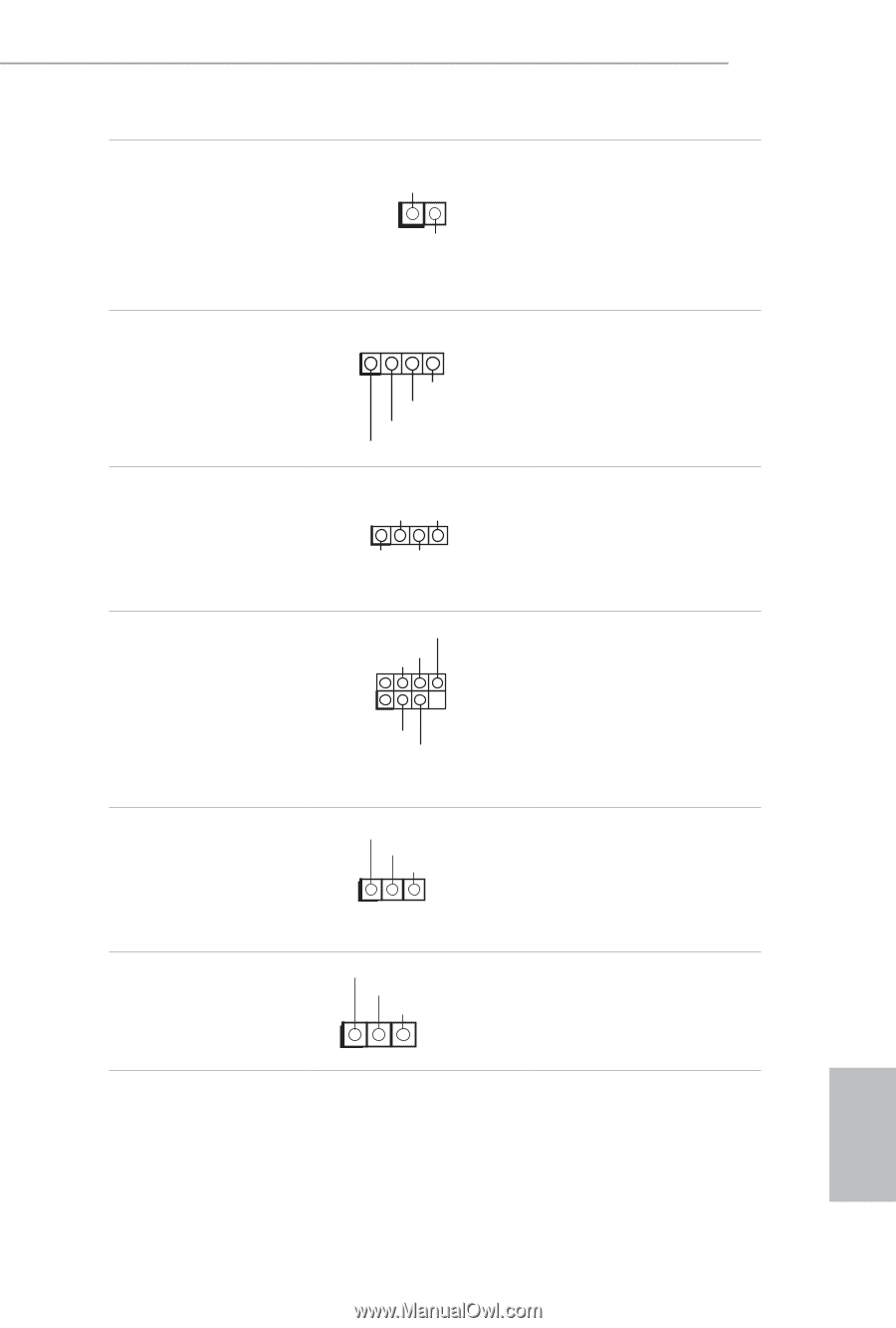
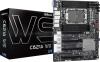
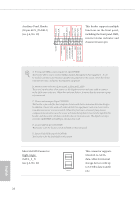
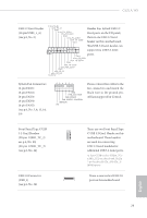
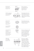
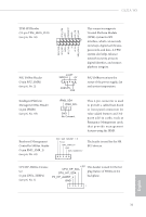
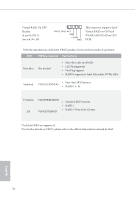
C621A WS Thermal Sensor Header (2-pin TR1) (see p.6, No. 39) Front LAN LED Header (4-pin FRONT_LED_ LAN34) (see p.6, No. 35) Chassis Speaker Header (4-pin SPEAKER1) (see p.6, No. 26) TR1 1 GND Please connect the thermal sensor cable to either pin 1-2 or pin 2-3 and the other end to the device which you wish to monitor its temperature. 1 LAN4_LINK LED_PWR LED_PWR LAN3_LINK This 4-pin connector is used for the front LAN status indicator. DUMMY SPEAKER 1 +5V DUMMY Please connect the chassis speaker to this header. Serial General Purpose Input/Output Headers (7-pin SATA_SGPIO1) (see p.6, No. 37) (7-pin SSATA_SGPIO1) (see p.6, No. 38) SCLOCK SLOAD GND 1 SDATAOUT GND The headers support Serial Link interface for onboard SATA connections. PWM Configuration Header (3-pin PWM_CFG1) (see p.6, No. 11) CPU VSENSE Header (3-pin CPU_VSENSE) (see p.6, No. 10) GND SMB_DATA_VSB SMB_CLK_VSB 1 This header is used for PWM configurations. H_VSENSEINPMAX_CPU1 GND GND 1 This header is used to detect CPU1 VSENSE. English 33
-
 1
1 -
2
-
3
-
4
-
5
-
6
-
7
-
8
-
9
-
10
-
11
-
12
-
13
-
14
-
15
-
16
-
17
-
18
-
19
-
20
-
21
-
22
-
23
-
24
-
25
-
26
-
27
-
28
-
29
-
30
-
31
-
32
-
33
-
 34
34 -
 35
35 -
 36
36 -
 37
37 -
 38
38 -
 39
39 -
 40
40 -
 41
41 -
 42
42 -
 43
43 -
 44
44 -
45
-
46
-
47
-
48
-
49
-
50
-
51
-
52
-
53
-
54
-
55
-
56
-
57
-
58
-
59
-
60
-
61
-
62
-
63
-
64
-
65
-
66
-
67
-
68
-
69
-
70
-
71
-
72
-
73
-
74
-
75
-
76
-
77
-
78
-
79
-
80
-
81
-
82
-
83
-
84
-
85
-
86
 |
 |