ASRock C621A WS User Manual - Page 36
ATX 12V Power
 |
View all ASRock C621A WS manuals
Add to My Manuals
Save this manual to your list of manuals |
Page 36 highlights
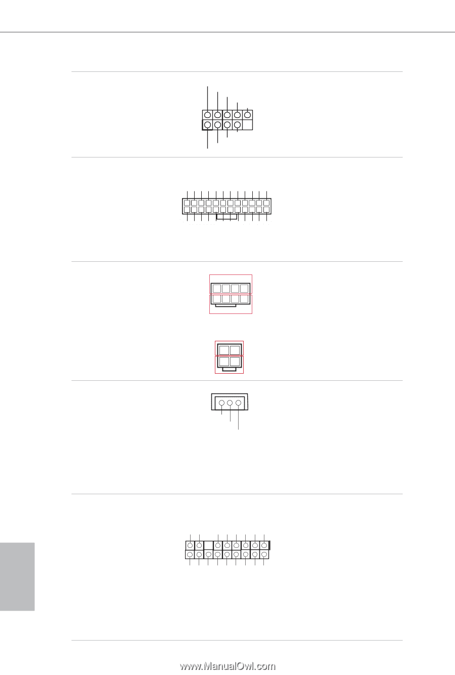
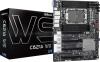
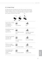
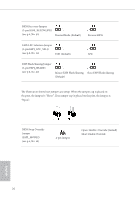
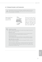
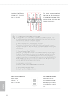
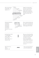
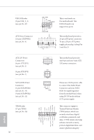
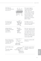
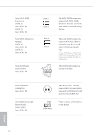
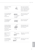
USB 2.0 Header (9-pin USB_2_3) (see p.6, No. 27) ATX Power Connector (24-pin ATXPWR1) (see p.6, No. 4) USB_PWR PP+ GND DUMMY 1 GND P+ PUSB_PWR This is one header on this motherboard. This USB 2.0 header can support two ports. 3V 12V 12V 5VSB PWROK_PS GND 5V GND 5V GND 3V 3V This motherboard provides a 24-pin ATX power connector. 1 12 To use a 20-pin ATX power 13 24 supply, please plug it along Pin 1 and Pin 13. GND 5V 5V 5V N/A GND GND GND PSON# GND -12V 3V ATX 12V Power Connectors (8-pin ATX12V1) (see p.6, No. 5) (4-pin ATX12V2) (see p.6, No. 7) SATA DOM Power Connector (3-pin SATAPWR1) (see p.6, No. 15) (3-pin SATAPWR2) (see p.6, No. 12) TPM Header (17-pin TPM1) (see p.6, No. 36) 30 GND SERIRQ# S_PWRDWN# GND LAD1 LAD2 SMB_DATA_MAIN SMB_CLK_MAIN GND GND +3VSB LAD0 +3V LAD3 PCIRST# LFRAME# PCICLK GND 1 4 5 8 12V GND 1 2 3 4 12V +5V GND +12V This motherboard provides one 8-pin and one 4-pin ATX 12V power connectors. Please use a SATA power cable to connect this SATA Power Connector and your SATA HDD for supplying power from the motherboard, when using DC-IN mode without SATA power supply. This connector supports Trusted Platform Module (TPM) system, which can 1 securely store keys, digital certificates, passwords, and data. A TPM system also helps enhance network security, protects digital identities, and ensures platform integrity. English
-
 1
1 -
2
-
3
-
4
-
5
-
6
-
7
-
8
-
9
-
10
-
11
-
12
-
13
-
14
-
15
-
16
-
17
-
18
-
19
-
20
-
21
-
22
-
23
-
24
-
25
-
26
-
27
-
28
-
29
-
30
-
 31
31 -
 32
32 -
 33
33 -
 34
34 -
 35
35 -
 36
36 -
 37
37 -
 38
38 -
 39
39 -
 40
40 -
 41
41 -
42
-
43
-
44
-
45
-
46
-
47
-
48
-
49
-
50
-
51
-
52
-
53
-
54
-
55
-
56
-
57
-
58
-
59
-
60
-
61
-
62
-
63
-
64
-
65
-
66
-
67
-
68
-
69
-
70
-
71
-
72
-
73
-
74
-
75
-
76
-
77
-
78
-
79
-
80
-
81
-
82
-
83
-
84
-
85
-
86
 |
 |