Alesis DM8 USB Kit Operation Manual - Page 8
Rear Panel Features, Top Panel Features - dm8 usb drum kit
 |
View all Alesis DM8 USB Kit manuals
Add to My Manuals
Save this manual to your list of manuals |
Page 8 highlights
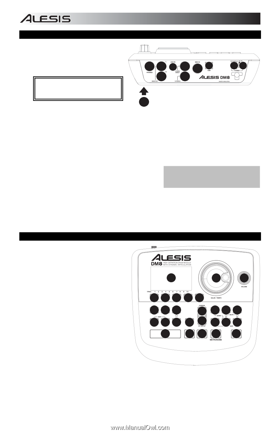
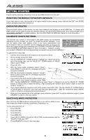
REAR PANEL FEATURES 1. POWER SWITCH - Turns the module on and off. 2. POWER IN - Connect the included AC adapter to this input, then connect the adapter to a power source. 934 8 65 3 8 21 WARNING: Use only the included Alesis power supply with the DM8 module. 3. MAIN OUT - Use 1/4" TRS cables to 7 connect these outputs to an amplifier or speaker system. The volume of these outputs is controlled by the VOLUME knob on the top panel. 4. AUX IN - Connect an external sound source, such as a CD player, to this input using a stereo 1/8" cable. 5. USB - Use a standard USB cable to connect the module to your computer via this USB port. This connection allows the module to send MIDI messages via USB to an external drum software module. You can also transmit SysEx files over this connection. 6. MIDI IN - Use a standard five-pin MIDI cable to connect this input to the MIDI OUT of an external MIDI device. 7. CABLE SNAKE CONNECTION - Connect the included Note: The module's HI-HAT CONTROL cable snake to this connector, then connect the cables TRIGGER INPUT does not support to their respective triggers. keyboard-style expression pedals. 8. TRIGGER INPUTS - If you have additional drum pads, cymbal pads, or other triggers, you can use standard 1/4" cables to connect them to the "RIDE 2/PERC1" or "PERC2" TRIGGER INPUTS. Dual-zone pads or cymbals (e.g., a drum with head and rim triggers or a cymbal that can produce bow and bell sounds) will require TRS cables to trigger both zones. 9. HEADPHONES OUTPUT - Connect your 1/4" headphones to this output. You can adjust the volume of this output with the VOLUME knob on the module's top panel. TOP PANEL FEATURES 1. VOLUME - Adjusts the volume level of the MAIN OUT and HEADPHONES OUTPUT. 2. METRONOME ON / OFF - Turns the metronome on or off. 3. LCD - Displays system menus, parameters, and other settings as you use the DM8. 4. F-BUTTONS (1-4) - These buttons allow you to navigate the menus shown in the LCD. Press an F-BUTTON to select the "virtual" button or tab shown above it in the LCD. 3 6 1 444 48 10 11 12 5 17 18 19 13 14 15 16 5 20 21 22 5. CURSOR UP / DOWN - Use these buttons to move (vertically) through the available parameters shown in menus in the LCD. 9 7 7 2 23 Note: Pressing CURSOR DOWN from the Main Screen allows you to adjust overall parameters for the current Kit. 6. VALUE DIAL - Turn this wheel to increase and decrease values and settings shown in the LCD. 7. VALUE UP / DOWN - Use these buttons to increase and decrease values and settings shown in the LCD. These may be easier to use than the VALUE DIAL when making incremental adjustments to your parameters. 8. EXIT - Press this button to return to the previous menu shown in the LCD. 8
-
 1
1 -
2
-
 3
3 -
 4
4 -
 5
5 -
 6
6 -
 7
7 -
 8
8 -
 9
9 -
 10
10 -
 11
11 -
 12
12 -
 13
13 -
14
-
15
-
16
-
17
-
18
-
19
-
20
-
21
-
22
-
23
-
24
-
25
-
26
-
27
-
28
-
29
-
30
-
31
-
32
-
33
-
34
-
35
-
36
-
37
-
38
-
39
-
40
-
41
-
42
-
43
-
44
-
45
-
46
-
47
-
48
 |
 |