Alesis MultiMix 8 Line Quick Start Guide - Page 4
Front Panel Overview - 8 channel stereo line mixer
 |
View all Alesis MultiMix 8 Line manuals
Add to My Manuals
Save this manual to your list of manuals |
Page 4 highlights
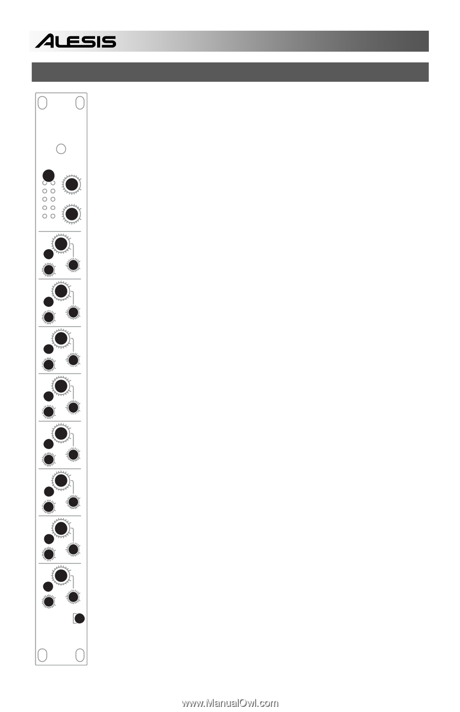
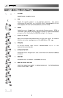
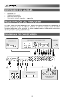
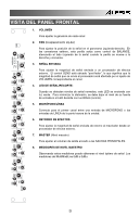
POWER MAX MIN 67 MAX EFFECTS RETURN MASTER +3dB +6dB 8 0dB MASTER LEVEL -5dB L -10dB MIN R MAX 1 SIG/ CLIP 4 CH 8 MIN R 2 PAN MAX L 3 SEND MIN MAX SIG/ CLIP 4 CH 7 1 MIN R 2 PAN MAX L 3 SEND MIN MAX SIG/ CLIP 4 CH 6 1 MIN R 2 PAN MAX L 3 SEND MIN MAX SIG/ CLIP 4 CH 5 1 FRONT PANEL OVERVIEW 1. VOLUME Adjust the gain for each channel 2. PAN Adjust the signal's position in the left-right panorama. For stereo connections, this knob acts as a BALANCE control, attenuating the left side of the signal as the knob is moved rightwards, and vice versa. 3. SEND Adjust the amount of signal sent to an external effects processor. SEND is "post-fader," which means that the amount of signal you send to the external processor will be affected by the VOLUME setting for the channel. 4. SIGNAL/CLIP LED When normal signal levels are detected, this LED glows green. To minimize distortion, turn down your input source if the LED flashes RED (clip). 5. MIC/LINE For the first channel, switch between a MICROPHONE input or the LINE inputs on the rear of the unit. 6. EFFECTS RETURN Adjust the amount of signal sent back to the mixer from an external effects processor. 7. MASTER Adjust the output volume sent to the MAIN OUTPUTS. 8. MASTER LEVEL METERS Watch the master level meters for optimal signal level. The MultiMix8Line's meters indicate 0dB at 0dBu. 4 MIN R 2 PAN MAX 3 L SEND MIN MAX SIG/ CLIP 4 CH 4 1 MIN R 2 PAN MAX L 3 SEND MIN MAX 1 SIG/ CLIP 4 CH 3 MIN R 2 PAN MAX L SEND 3 MIN MAX 1 SIG/ CLIP 4 CH 2 MIN R 2 PAN MAX L SEND 3 MIN 1 SIG/ CLIP 4 CH 1 MIN 2 PAN MAX SEND 3 MIN MIC/LINE 5
-
 1
1 -
 2
2 -
 3
3 -
 4
4 -
 5
5 -
 6
6 -
 7
7 -
 8
8 -
 9
9 -
 10
10 -
11
-
12
-
13
-
14
-
15
-
16
-
17
-
18
-
19
-
20
-
21
-
22
-
23
-
24
-
25
-
26
-
27
-
28
 |
 |