Alesis MultiMix 8 Line Quick Start Guide - Page 5
Rear Panel Overview - stereo line mixer
 |
View all Alesis MultiMix 8 Line manuals
Add to My Manuals
Save this manual to your list of manuals |
Page 5 highlights
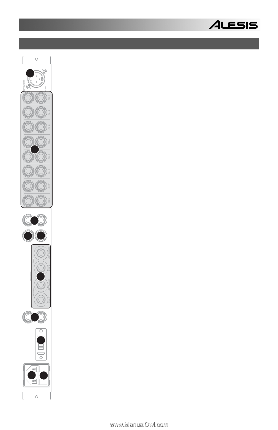
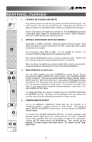
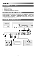
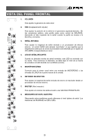
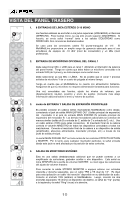
LEFT (MONO) MIC 2 RIGHT CH 1 CH 2 CH 3 CH 4 1 CH 5 CH 6 CH 7 CH 8 OUT 3 IN MAIN EXPAND FX BUS LINK REAR PANEL OVERVIEW 1. 8 STEREO OR 16 MONO LINE INPUTS Plug stereo sources into both the top (LEFT) and bottom (RIGHT) jacks. For mono sources, use only the top (LEFT) jack. Doing this will "normal" the signal to both LEFT and RIGHT inputs. These are unbalanced connections. Use TS (Tip-sleeve) 1/4" cables for connections. The MultiMix8Line provides a wide gain range suitable for simultaneous use of both -10dbV (consumerlevel) and +4dBu (professional-level) equipment. 2. OPTIONAL MICROPHONE INPUT ON CHANNEL 1 Select MIC or LINE for channel 1 using the switch on the front panel. Note that a microphone must be connected to the XLR (3-pin) input and is always treated as a mono signal. You must select either MIC or LINE. It is not possible for channel 1 to process microphone AND quarter-inch signals at one time. Note that the MultiMix8Line does not feature phantom power. Ensure that your microphone does not require phantom power for operation. Once you have connected your sources, adjust their volume, pan position, and aux send levels. (See below for more on Aux Send and Return.) 3. MAIN EXPAND IN and OUT jacks You can chain together as many MultiMix8Line mixers as you like by connecting the MAIN EXPAND OUT jack of mixer A into the MAIN EXPAND IN jack of mixer B. Continue connecting additional mixers in similar fashion (OUT B into IN C, OUT C into IN D, etc.). Use a stereo (TRS) cable for these connections. The final mixer in the chain will control the MASTER volume for all of the devices connected to all the mixers. Connect the final mixer in the chain to your output device (amplifier, powered speakers, main mixer, etc.) via the MAIN OUTPUT jacks. The MAIN EXPAND OUT signal is tapped before the EFFECTS RETURN and MASTER controls. Therefore, for any particular mixer, any signal sent from this jack will not be affected by the position of these controls. 4. STEREO MONITOR OUTPUT This is an additional, unbalanced output that you can connect to a headphone amplifier, auxiliary recorder, or other device. This signal is tapped AFTER the MASTER volume knob: its level follows the MASTER volume setting. To connect the STEREO MONITOR OUTPUT to stereo equipment with separate Left and Right inputs, use a TRS-to-dual-TS 1/4" cable. A standard "Insert" cable, available from your audio dealer, is ideal for this application. Connect the TRS (stereo) plug to the MultiMix8Line. Then, connect the two separate TS (mono) plugs to the target device, "Tip" signal Left and "Ring" signal Right. 5 5 4 STEREO MONITOR LEFT (MONO) SEND RIGHT EFFECTS 6 LEFT (MONO) RETURN RIGHT LEFT 7 RIGHT MAIN OUT 8 INPUT VOLTAGE 1 0 9 FUSE F0.5AL,250V AC INPUT 115/230V
-
 1
1 -
 2
2 -
 3
3 -
 4
4 -
 5
5 -
 6
6 -
 7
7 -
 8
8 -
 9
9 -
 10
10 -
 11
11 -
12
-
13
-
14
-
15
-
16
-
17
-
18
-
19
-
20
-
21
-
22
-
23
-
24
-
25
-
26
-
27
-
28
 |
 |