Ariens Deluxe Track 28 Owners Manual - Page 32
Attachment Drive Belt, Replacement
 |
View all Ariens Deluxe Track 28 manuals
Add to My Manuals
Save this manual to your list of manuals |
Page 32 highlights
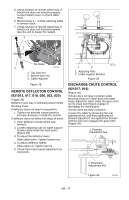
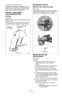
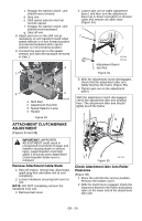
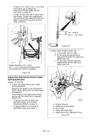
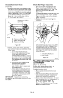
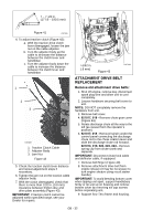
7 - 7-1/2 in. (177.8 - 190.5 mm) Figure 41 OS7206 4. To adjust traction clutch (Figure 42): a. With the traction drive clutch lever disengaged, loosen the jam nut on the cable adjuster. b. Turn the adjuster body up the cable to decrease the distance between the clutch lever and handlebar. c. Turn the adjuster body down the cable to increase the distance between the clutch lever and handlebar. 1 2 3 OS7208 1. Traction Clutch Cable 2. Adjuster Body 3. Jam Nut Figure 42 5. Check the traction clutch lever distance and repeat adjustment steps if necessary. 6. Tighten the jam nut on the traction cable adjustor body. 7. With the clutch disengaged, check that there is more than 1/32 in. (0.8 mm) clearance between friction disc and drive plate assembly (Figure 43). IMPORTANT: If traction clutch cannot be adjusted within specified range, see your Dealer for repairs. >1/32 in. (.8 mm) Figure 43 OS7144 ATTACHMENT DRIVE BELT REPLACEMENT Remove old attachment drive belts: 1. Shut off engine, remove key, disconnect spark plug wire and allow unit to cool completely. 2. Loosen hardware securing belt cover to unit. NOTE: DO NOT completely remove the hardware from unit. 3. Remove belt cover. 4. 921017, 018 - Remove chute gear cover (Figure 44). 5. Rotate discharge chute all the way to the left (as viewed from the operator's position). 6. 921017, 018 - Remove hairpin under the control panel connecting the discharge chute rod to the chute rotation lever and slide the discharge chute rod forward. 921013, 019, 020, 022, 023 - Remove spring clip from chute crank and separate. IMPORTANT: Disconnect chute lock cable and deflector cable, if equipped. 7. Remove belt finger (Figure 40). 8. Remove attachment drive belt from engine sheave (it may be necessary to turn engine sheave using recoil starter handle). IMPORTANT: To avoid bending bottom cover when tipping unit apart, support handlebars firmly or tip unit up on housing and remove bottom cover by removing six cap screws before separating unit. 9. Support Sno-Thro frame and housing. GB - 32
-
 1
1 -
2
-
3
-
4
-
5
-
6
-
7
-
8
-
9
-
10
-
11
-
12
-
13
-
14
-
15
-
16
-
17
-
18
-
19
-
20
-
21
-
22
-
23
-
24
-
25
-
26
-
 27
27 -
 28
28 -
 29
29 -
 30
30 -
 31
31 -
 32
32 -
 33
33 -
 34
34 -
 35
35 -
 36
36 -
 37
37 -
38
-
39
-
40
-
41
-
42
 |
 |
