Ariens Deluxe Track 28 Owners Manual - Page 33
Traction Drive Belt, Replacement
 |
View all Ariens Deluxe Track 28 manuals
Add to My Manuals
Save this manual to your list of manuals |
Page 33 highlights
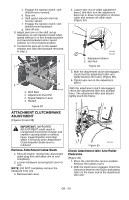
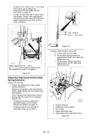
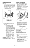
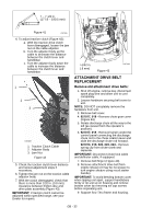
CAUTION: Always support SnoThro frame and blower housing when loosening the cap screws holding them together. Never loosen cap screws while unit is in service position. 10. Remove hex bolts securing housing to frame (two on each side). Tip housing and frame apart on pivot pin (Figure 44). 11. Remove attachment drive belts from attachment pulley (hold brake away from belt). 921013, 019, 020, 022, 023 4. Reposition and secure belt finger. IMPORTANT: With clutch lever engaged, belt finger on the side opposite the belt idler should be less than 1/8 in. (3 mm) from belt, but not touching the belt. Adjust belt finger as necessary. 2 1 2 3 1 921017, 018 2 3 7 4 5 1. Traction Drive Belt 2. Engine Sheave 3. Attachment Drive Belts 4. Belt Finger 3 6 5. Attachment Belt Idler 6. Attachment Idler Adjustment Nut 7. Traction Belt Idler Figure 45 1 4 1. Belt Cover 2. Chute Gear Cover 3. Discharge Chute Rod 4. Chute Lock Cable Figure 44 Install new attachment drive belts: 1. Place new attachment belts onto attachment pulley. NOTE: Holding down the attachment clutch lever will make it easier to reconnect the housing and frame. 2. Tip housing and frame back together and secure with hex bolts. 3. Place belts onto engine sheave. 5. Check adjustment. See Attachment Clutch/Brake Adjustment on page 29. WARNING: AUGER / IMPELLER MUST STOP within 5 seconds when attachment clutch lever is released or unit damage or serious injury may result. 6. Reconnect chute crank and secure with spring clip (921013, 019, 020, 022, 023) or hairpin (921017, 018). IMPORTANT: Reconnect chute lock cable and deflector cable (if equipped). 7. Replace belt cover and tighten hardware. TRACTION DRIVE BELT REPLACEMENT NOTE: Replacement will be easier with housing and frame tipped apart and bottom cover off. 1. Remove attachment drive belts (see Attachment Drive Belt Replacement on page 32). GB - 33
-
 1
1 -
2
-
3
-
4
-
5
-
6
-
7
-
8
-
9
-
10
-
11
-
12
-
13
-
14
-
15
-
16
-
17
-
18
-
19
-
20
-
21
-
22
-
23
-
24
-
25
-
26
-
27
-
 28
28 -
 29
29 -
 30
30 -
 31
31 -
 32
32 -
 33
33 -
 34
34 -
 35
35 -
 36
36 -
 37
37 -
 38
38 -
39
-
40
-
41
-
42
 |
 |
