Ariens Deluxe Track 28 Owners Manual - Page 8
Assembly
 |
View all Ariens Deluxe Track 28 manuals
Add to My Manuals
Save this manual to your list of manuals |
Page 8 highlights
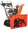
ASSEMBLY WARNING: AVOID INJURY. Read and understand the entire Safety section before proceeding. WARNING: Dropping or tipping over boxed unit could result in personal injury or damage to unit. PACKAGE CONTENTS 921013, 019, 020, 022, 023 3 2 1 4, 5 OS7021 1. Sno-Thro Unit 2. Discharge Chute 3. Chute Crank 4. Literature Pack with Extra Shear Bolts 5. Fuel Cap (921020) Figure 3 2 4 921017, 018 3 1 1. Sno-Thro Unit 2. Discharge Chute 3. Chute Rod 4. Literature Pack with Extra Shear Bolts Figure 4 OS7019 ASSEMBLY Tools Required: • Pliers • Open-End Wrenches: 3/8, 7/16, 1/2, 9/16 in. and/or Adjustable Wrench • Tire Gauge Unfold Handlebar (Figure 5) 1. Remove the lower and loosen the upper hardware on the handlebar assembly. 2. Loosen the hardware on the shift rod. 3. Put the speed selector lever in the: 921013, 017, 018, 020, 023 - second reverse position. 921019, 022 - fastest forward position. 4. Rotate the handlebars into operating position. IMPORTANT: Be careful not to damage cable spring hooks when rotating handlebars upward. 5. Install and tighten all hardware on the handlebar assembly and shift rod. GB - 8
-
 1
1 -
2
-
 3
3 -
 4
4 -
 5
5 -
 6
6 -
 7
7 -
 8
8 -
 9
9 -
 10
10 -
 11
11 -
 12
12 -
 13
13 -
14
-
15
-
16
-
17
-
18
-
19
-
20
-
21
-
22
-
23
-
24
-
25
-
26
-
27
-
28
-
29
-
30
-
31
-
32
-
33
-
34
-
35
-
36
-
37
-
38
-
39
-
40
-
41
-
42
 |
 |
