Asus A7S-VM A7S-VM User Manual - Page 15
ASUS A7S-VM User's Manual, Motherboard Settings, Expansion Slots/Sockets, External Connectors, - socket a motherboard
 |
View all Asus A7S-VM manuals
Add to My Manuals
Save this manual to your list of manuals |
Page 15 highlights
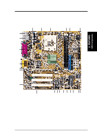
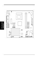
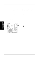
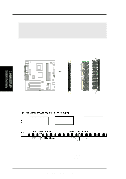
3. HARDWARE SETUP 3.2 Layout Contents 3. H/W SETUP Layout Contents Motherboard Settings 1) USB_UP 2) KB_UP 3) CLR_CMOS Expansion Slots/Sockets 1) DIMM 1/2 2) Socket A 3) PCI 1/2/3/4 External Connectors 1) PS2KBMS 2) PS2KBMS 3) RJ-45 4) USB 5) PRINTER 6) COM1 7) VGA 8) GAME_AUDIO (Top) 9) GAME_AUDIO (Bottom) Internal Connectors 1) IDELED 2) FLOPPY 3) PRIMARY IDE SECONDARY IDE 4) WOL_CON 5) WOR 6) CPU/PWR/CHA_FAN 7) CHASSIS 8) SMB 9) IR 10) CIR 11) AFPANEL 12) AAPANEL 13) USBP1/USBP2 14) CD/VIDEO/AUX/MODEM 15) TV-LCD 16) COM2 17) ATXPWR 18) PWR_TMP 19) PWR.LED (PANEL) 20) SPEAKER (PANEL) 21) MSG.LED (PANEL) 22) SMI (PANEL) 23) PWR.SW (PANEL) 24) RESET (PANEL) p. 17 USB Wake Up Jumper p. 17 Keyboard Wake-up Jumper p. 18 Clear RTC RAM p. 19 System Memory Support p. 21 CPU Support p. 23 32-bit PCI Bus Expansion Slots p. 25 PS/2 Mouse Port (6-pin female) p. 25 PS/2 Keyboard Port (6-pin female) p. 25 Fast Ethernet LAN Port (RJ-45) p. 26 Universal Serial Bus Ports 1 & 2 (two 4-pin female) p. 26 Parallel Port (25-pin female) p. 26 Serial Ports (9-pin /10-1 pin male) p. 27 Video Port (15-pin female) p. 27 Game/MIDI Port (15-pin femal) p. 27 Audio Ports (1/8" jacks) p. 28 IDE Activity LED (2-pin) p. 28 Floppy Disk Drive Connector (34-pin) p. 29 IDE Connectors (two 40-1 pin) p. 30 Wake-On-LAN Connector (3-pin) p. 30 Wake-On-Ring Connector (2-pin) p. 31 CPU, Power, and Chassis Fan Connectors (3-pin) p. 32 Chassis Intrusion Lead (4-1 pin) p. 32 SMBus Connector (5-1 pin) p. 33 Standard Infrared Module Connector (5-pin) p. 33 Consumer Infrared Module Connector (5-pin) p. 34 ASUS iPanel Connector (12-1 pin) p. 34 Audio Panel Connector (12-1 pin) p. 35 USB Headers (two 10-1 pin) p. 35 Internal Audio Connectors (4-1 pin) p. 36 LCD Headers (two 20-pin) p. 36 Serial Port 2 Connector (10-1 pin) p. 37 ATX Power Supply Connector (20-pin) p. 37 Power Supply Thermal Sensor Conn. (2-pin) p. 38 System Power LED Lead (3-pin) p. 38 System Warning Speaker Lead (4-pin) p. 38 System Message LED Lead (2-pin) p. 38 System Management Interrupt Lead (2-pin) p. 38 ATX / Soft-Off Switch Lead (2-pin) p. 38 Reset Switch Lead (2-pin) ASUS A7S-VM User's Manual 15
-
 1
1 -
2
-
3
-
4
-
5
-
6
-
7
-
8
-
9
-
 10
10 -
 11
11 -
 12
12 -
 13
13 -
 14
14 -
 15
15 -
 16
16 -
 17
17 -
 18
18 -
 19
19 -
 20
20 -
21
-
22
-
23
-
24
-
25
-
26
-
27
-
28
-
29
-
30
-
31
-
32
-
33
-
34
-
35
-
36
-
37
-
38
-
39
-
40
-
41
-
42
-
43
-
44
-
45
-
46
-
47
-
48
-
49
-
50
-
51
-
52
-
53
-
54
-
55
-
56
-
57
-
58
-
59
-
60
-
61
-
62
-
63
-
64
-
65
-
66
-
67
-
68
-
69
-
70
-
71
-
72
-
73
-
74
-
75
-
76
-
77
-
78
-
79
-
80
-
81
-
82
-
83
-
84
-
85
-
86
-
87
-
88
-
89
-
90
 |
 |
