Asus A7S-VM A7S-VM User Manual - Page 36
ASUS A7S-VM User's Manual, LCD/TV Interface Connectors two 20-pin TV-LCD, Serial Port 2 Connector 10
 |
View all Asus A7S-VM manuals
Add to My Manuals
Save this manual to your list of manuals |
Page 36 highlights
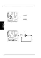
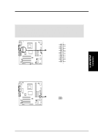
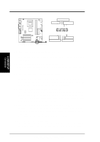
3. HARDWARE SETUP 15) LCD/TV Interface Connectors (two 20-pin TV-LCD) These 20-pin connectors accommodate the PC to ASUS TV301 daughter card. The daughter card includes LCD and TV output headers for LCD monitor or TV connection. (NOTE: The ASUS TV301 daughter card does not come with the motherboard package). 1 TV-LCD A7S-VM A7S-VM TV-LCD Headers 16) Serial Port 2 Connector (10-1 pin COM2) This connector accommodates a second serial port using an optional serial port bracket. Connect the bracket cable to this connector then install the bracket into a slot opening at the back of the system chassis. COM2 PIN 1 A7S-VM A7S-VM Serial COM2 Bracket 3. H/W SETUP Connectors 36 ASUS A7S-VM User's Manual
-
 1
1 -
2
-
3
-
4
-
5
-
6
-
7
-
8
-
9
-
10
-
11
-
12
-
13
-
14
-
15
-
16
-
17
-
18
-
19
-
20
-
21
-
22
-
23
-
24
-
25
-
26
-
27
-
28
-
29
-
30
-
 31
31 -
 32
32 -
 33
33 -
 34
34 -
 35
35 -
 36
36 -
 37
37 -
 38
38 -
 39
39 -
 40
40 -
 41
41 -
42
-
43
-
44
-
45
-
46
-
47
-
48
-
49
-
50
-
51
-
52
-
53
-
54
-
55
-
56
-
57
-
58
-
59
-
60
-
61
-
62
-
63
-
64
-
65
-
66
-
67
-
68
-
69
-
70
-
71
-
72
-
73
-
74
-
75
-
76
-
77
-
78
-
79
-
80
-
81
-
82
-
83
-
84
-
85
-
86
-
87
-
88
-
89
-
90
 |
 |

36
ASUS A7S-VM User’s Manual
3. HARDWARE SETUP
Connectors
3. H/W SETUP
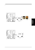
15) LCD/TV Interface Connectors (two 20-pin TV-LCD)
These 20-pin connectors accommodate the PC to ASUS TV301 daughter card.
The daughter card includes LCD and TV output headers for LCD monitor or TV
connection. (
NOTE:
The ASUS TV301 daughter card does not come with the
motherboard package).
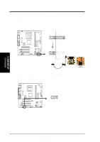
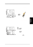
A7S-VM
A7S-VM Serial COM2 Bracket
PIN 1
COM2
A7S-VM
A7S-VM TV-LCD Headers
1
TV-LCD
16) Serial Port 2 Connector (10-1 pin COM2)
This connector accommodates a second serial port using an optional serial port
bracket. Connect the bracket cable to this connector then install the bracket into
a slot opening at the back of the system chassis.