Asus A7S-VM A7S-VM User Manual - Page 35
ASUS A7S-VM User's Manual, Internal Audio and Video Connectors 4-1 pin CD, VIDEO, AUX, MODEM, USB - a7s video black
 |
View all Asus A7S-VM manuals
Add to My Manuals
Save this manual to your list of manuals |
Page 35 highlights
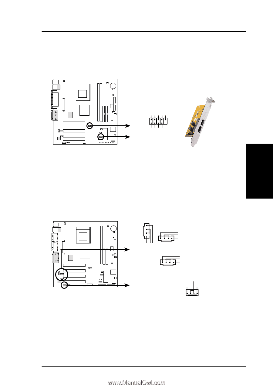
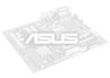
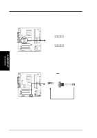
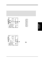
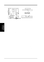
3. H/W SETUP Connectors 3. HARDWARE SETUP 13) USB Headers (10-1 pin USBP1, USBP2) If the USB ports on the back panel are inadequate, two USB headers are available for four additional USB ports. Connect a 2-port USB connector set to one USB header then mount the bracket to an open slot on the chassis. (NOTE: The USB connector set does not come with the motherboard package.) USBP1 USBP2 USB Power USBP2- USBP2+ GND NC 1 5 6 10 USB Power USBP3- USBP3+ GND A7S-VM A7S-VM USB Port 14) Internal Audio and Video Connectors (4-1 pin CD, VIDEO, AUX, MODEM) These connectors allow you to receive stereo audio input from sound sources such as a CD-ROM, TV tuner, or MPEG card. The MODEM connector allows the onboard audio to interface with a voice modem card with a similar connector. It also allows the sharing of mono_in (such as a phone) and a mono_out (such as a speaker) between the audio and the voice modem card. CD (Black) A7S-VM A7S-VM Internal Audio Connectors Left Audio Channel Ground Right Audio Channel VIDEO (Green) Left Audio Channel Ground Right Audio Channel AUX (White) Left Audio Channel Ground Right Audio Channel MODEM Ground Modem-In Modem-Out (to Modem) (from Modem) ASUS A7S-VM User's Manual 35
-
 1
1 -
2
-
3
-
4
-
5
-
6
-
7
-
8
-
9
-
10
-
11
-
12
-
13
-
14
-
15
-
16
-
17
-
18
-
19
-
20
-
21
-
22
-
23
-
24
-
25
-
26
-
27
-
28
-
29
-
 30
30 -
 31
31 -
 32
32 -
 33
33 -
 34
34 -
 35
35 -
 36
36 -
 37
37 -
 38
38 -
 39
39 -
 40
40 -
41
-
42
-
43
-
44
-
45
-
46
-
47
-
48
-
49
-
50
-
51
-
52
-
53
-
54
-
55
-
56
-
57
-
58
-
59
-
60
-
61
-
62
-
63
-
64
-
65
-
66
-
67
-
68
-
69
-
70
-
71
-
72
-
73
-
74
-
75
-
76
-
77
-
78
-
79
-
80
-
81
-
82
-
83
-
84
-
85
-
86
-
87
-
88
-
89
-
90
 |
 |