Asus A7S-VM A7S-VM User Manual - Page 32
ASUS A7S-VM User's Manual, Chassis Intrusion Lead 4-1 pin CHASSIS, SMBus Connector 5-1 pin SMB
 |
View all Asus A7S-VM manuals
Add to My Manuals
Save this manual to your list of manuals |
Page 32 highlights
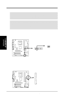
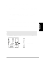
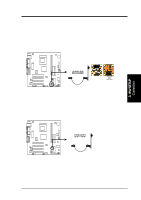
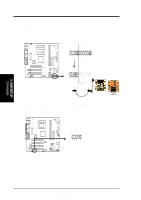
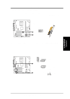
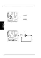
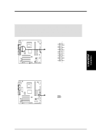
Ground Chassis Signal +5Volt (Power Supply Stand By) 3. H/W SETUP Connectors 3. HARDWARE SETUP 7) Chassis Intrusion Lead (4-1 pin CHASSIS) This lead is for a chassis designed for chassis intrusion detection. This requires an external detection mechanism such as a chassis intrusion monitor/sensor or microswitch. When any chassis component is removed, the sensor is triggered and a high-level signal is sent to this lead to record a chassis intrusion event.The event is then processed by software such as LDCM. When not using the chassis intrusion lead, place a jumper cap over the pins to close the circuit. CHASSIS 1 A7S-VM A7S-VM Chassis Open Alarm Lead 8) SMBus Connector (5-1 pin SMB) This connector allows you to connect SMBus (System Management Bus) devices. SMBus devices communicate by means of the SMBus with an SMBus host and/ or other SMBus devices. SMBus is a specific implementation of an I2C bus, which is a multi-device bus; that is, multiple chips can be connected to the same bus and each one can act as a master by initiating data transfer. SMB A7S-VM A7S-VM SMBus Connector 1 SMBCLK Ground SMBDATA +5V 32 ASUS A7S-VM User's Manual
-
 1
1 -
2
-
3
-
4
-
5
-
6
-
7
-
8
-
9
-
10
-
11
-
12
-
13
-
14
-
15
-
16
-
17
-
18
-
19
-
20
-
21
-
22
-
23
-
24
-
25
-
26
-
 27
27 -
 28
28 -
 29
29 -
 30
30 -
 31
31 -
 32
32 -
 33
33 -
 34
34 -
 35
35 -
 36
36 -
 37
37 -
38
-
39
-
40
-
41
-
42
-
43
-
44
-
45
-
46
-
47
-
48
-
49
-
50
-
51
-
52
-
53
-
54
-
55
-
56
-
57
-
58
-
59
-
60
-
61
-
62
-
63
-
64
-
65
-
66
-
67
-
68
-
69
-
70
-
71
-
72
-
73
-
74
-
75
-
76
-
77
-
78
-
79
-
80
-
81
-
82
-
83
-
84
-
85
-
86
-
87
-
88
-
89
-
90
 |
 |
