Asus AP1720-E2 AP1720-E2 English version manual - Page 37
the drive aligns to the rear edge
 |
View all Asus AP1720-E2 manuals
Add to My Manuals
Save this manual to your list of manuals |
Page 37 highlights
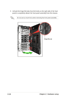
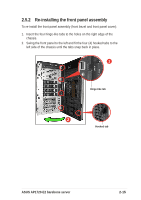
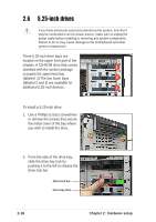
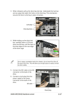
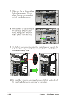
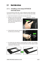
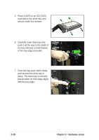
3. When released, pull up the drive bay lock bar. Underneath the lock bar are two pegs that match the holes on the drive bay. This mechanism secures the drive to the bay in place of screws. Lock pegs Drive bay holes 4. While holding up the drive lock bar, carefully insert a 5.25-inch drive into the bay, until the back of the drive aligns to the rear edge of the drive cage. Due to space constraints inside the chassis, do not insert the drive all the way at this time. This will allow you enough space to easily connect the drive cables. 5. Connect the IDE cable to the IDE connector on the back of the drive. 6. Connect a 4-pin plug from the power supply to the power connector on the back of the drive. IDE cable ASUS AP1720-E2 barebone server Power plug 2-17
-
 1
1 -
2
-
3
-
4
-
5
-
6
-
7
-
8
-
9
-
10
-
11
-
12
-
13
-
14
-
15
-
16
-
17
-
18
-
19
-
20
-
21
-
22
-
23
-
24
-
25
-
26
-
27
-
28
-
29
-
30
-
31
-
 32
32 -
 33
33 -
 34
34 -
 35
35 -
 36
36 -
 37
37 -
 38
38 -
 39
39 -
 40
40 -
 41
41 -
 42
42 -
43
-
44
-
45
-
46
-
47
-
48
-
49
-
50
-
51
-
52
-
53
-
54
-
55
-
56
-
57
-
58
-
59
-
60
-
61
-
62
-
63
-
64
-
65
-
66
-
67
-
68
-
69
-
70
-
71
-
72
-
73
-
74
-
75
-
76
-
77
-
78
-
79
-
80
-
81
-
82
-
83
-
84
-
85
-
86
-
87
-
88
-
89
-
90
-
91
-
92
-
93
-
94
-
95
-
96
-
97
-
98
-
99
-
100
-
101
-
102
-
103
-
104
-
105
-
106
-
107
-
108
-
109
-
110
-
111
-
112
-
113
-
114
-
115
-
116
-
117
-
118
-
119
-
120
-
121
-
122
-
123
-
124
-
125
-
126
-
127
-
128
-
129
-
130
-
131
-
132
-
133
-
134
-
135
-
136
-
137
-
138
-
139
-
140
-
141
-
142
-
143
-
144
-
145
-
146
-
147
-
148
-
149
-
150
-
151
-
152
-
153
-
154
-
155
-
156
 |
 |
