Asus AP200 Hardware Reference - Page 18
Removing the Front & Top Panels, Device Bay Covers
 |
View all Asus AP200 manuals
Add to My Manuals
Save this manual to your list of manuals |
Page 18 highlights
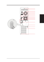
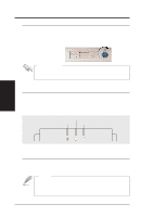
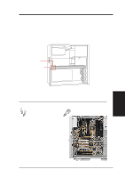
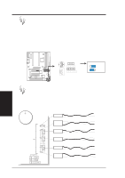
IV. Hardware Setup Removing the Front & Top Panels Before removing the front panel, the top panel must be unscrewed and removed. Lean the front panel over the edge of a table or book. Reach your fingers up into the front panel and pull the front panel away from the chassis. IV. HW Setup Chassis Removing the Front Panel Four of your fingers should fit behind the front panel. Device Bay Covers With the front panel removed, the device bay covers can be removed or installed. Device Bay Removal Procedure: 1. With your thumb, push the tab outward against the side of the front panel. 2. With your other hand, push the device cage cover inward from the front side. Device Bay Cover Tab Front Panel Backside 18 AP200 Hardware Reference Guide
-
 1
1 -
2
-
3
-
4
-
5
-
6
-
7
-
8
-
9
-
10
-
11
-
12
-
 13
13 -
 14
14 -
 15
15 -
 16
16 -
 17
17 -
 18
18 -
 19
19 -
 20
20 -
 21
21 -
 22
22 -
 23
23 -
24
-
25
-
26
-
27
-
28
-
29
-
30
-
31
-
32
 |
 |
18
IV. Hardware Setup
AP200 Hardware Reference Guide
IV. HW Setup
Chassis
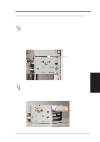
Removing the Front & Top Panels
Before removing the front panel, the top panel must be unscrewed and re-
moved. Lean the front panel over the edge of a table or book. Reach your
fingers up into the front panel and pull the front panel away from the chassis.
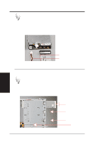
Device Bay Covers
With the front panel removed, the device bay covers can be removed or installed.
Device Bay Removal Procedure:
1.
With your thumb, push the tab outward against the side of the front panel.
2.
With your other hand, push the device cage cover inward from the front side.
Removing the Front Panel
Four of your fingers should fit
behind the front panel.
Front Panel Backside
Device Bay Cover Tab