Asus AP200 Hardware Reference - Page 20
Chassis Intrusion Photo Sensor, Panel Connections
 |
View all Asus AP200 manuals
Add to My Manuals
Save this manual to your list of manuals |
Page 20 highlights
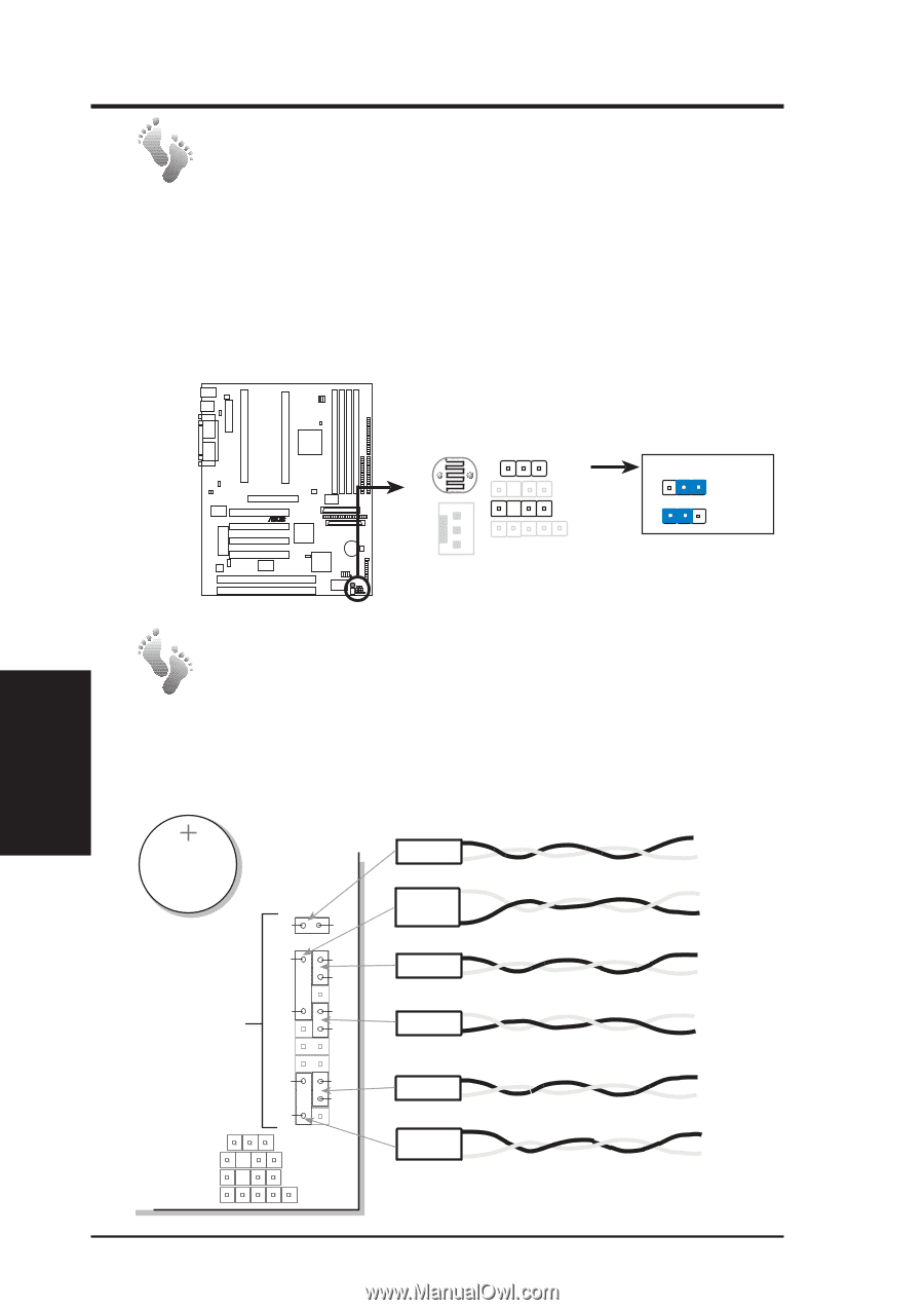
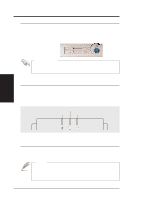
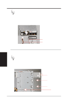
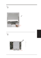
IV. Hardware Setup Chassis Intrusion Photo Sensor This motherboard has a photo sensor onboard, which detects extreme levels of light entering the chassis such as when the chassis is opened, and sends a signal to the ASMA software in such an event. To enable this function, Jumper18 must be set to Enable and an external battery must be connected to the motherboard's external battery connector. If you want to work on the inside of the chassis when an external battery is connected, you should disable Jumper18 to save the battery power. 1 R 1 Chassis Intrusion Photo Sensor Photo Sensor Setting JP18 EXTBATT JP18 Disable 123 Enable IV. HW Setup Motherboard P2B-D/DS Chassis Intrusion Photo Sensor Panel Connections Several wires should be connected to the motherboard for the IDE/SCSI activity, power, and message indicators on the front panel. Panel connections also allow for an ATX power button, reset switch, and speaker. Connect the chassis front panel wires as illustrated: Button Cell Battery for motherboard BIOS and clock White Black White Chassis Panel Connectors JP18 EXTBATT IR Green White Red Violet White Red Black Yellow White Red (+) H.D.D. LED White Black (+) Speaker White Violet (+) Reset SW White Red (+) Power SW Black Yellow (+) Turbo LED White Green (+) Power LED White 20 AP200 Hardware Reference Guide
-
 1
1 -
2
-
3
-
4
-
5
-
6
-
7
-
8
-
9
-
10
-
11
-
12
-
13
-
14
-
 15
15 -
 16
16 -
 17
17 -
 18
18 -
 19
19 -
 20
20 -
 21
21 -
 22
22 -
 23
23 -
 24
24 -
 25
25 -
26
-
27
-
28
-
29
-
30
-
31
-
32
 |
 |