Asus AP2300 AP2300 Server in English - Page 31
Front Cooling Fan Control Board, Hard Disk Drive Message Board
 |
View all Asus AP2300 manuals
Add to My Manuals
Save this manual to your list of manuals |
Page 31 highlights
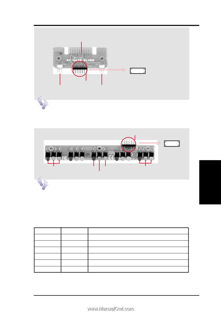
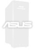
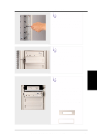
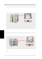
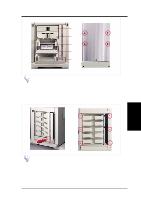
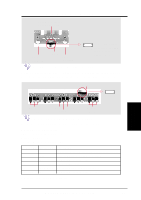
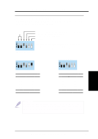
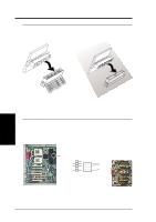
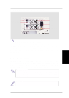
4. Hardware Setup Connects to the SCSI Back plane Board 4. Hardware Setup Front Cooling Fans 8 16 3-pin Fan Header Pin 1 3-pin Fan Header 1 LED Board Header 9 (connects to the LED board through a ribbon cable) Front Cooling Fan Control Board A cable connects the front cooling fan control board and the hard disk drive message board. Orient the red markings on each end of the cable to pin 1. Pin 1 8 1 16 9 First Set of LEDs Red Yellow Green Fifth Set of LEDs Hard Disk Drive Message Board Orient the red markings on the other end of the cable to pin 1. Message LED Description Red: Hard Disk Status LED Green: Power LED Yellow: Hard Disk Access LED Power LED Status LED Description Off Off Power subsystem OK and ready for hard drive insertion On Off Hard disk drive is ready for operation On On Hard disk drive failure (*) On Fast Flash RAID is rebuilding (*) On Slow Flash Hot-spare hard disk drive ready (*) Fast Flash On Hard disk drive failure/short circuits * Must work with ASMA software. AP2300 Hardware Reference Guide 31
-
 1
1 -
2
-
3
-
4
-
5
-
6
-
7
-
8
-
9
-
10
-
11
-
12
-
13
-
14
-
15
-
16
-
17
-
18
-
19
-
20
-
21
-
22
-
23
-
24
-
25
-
 26
26 -
 27
27 -
 28
28 -
 29
29 -
 30
30 -
 31
31 -
 32
32 -
 33
33 -
 34
34 -
 35
35 -
 36
36 -
37
-
38
-
39
-
40
-
41
-
42
-
43
-
44
 |
 |