Asus AP8000 Hardware Reference - Page 25
Floppy Disk, Drive, CD-ROM Drive
 |
View all Asus AP8000 manuals
Add to My Manuals
Save this manual to your list of manuals |
Page 25 highlights
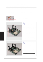
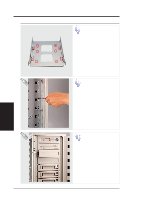
IV. Hardware Setup • 4-7. Floppy Disk Drive and CD-ROM Floppy Disk Drive The floppy drive fits in the topmost bay along with the power button. A metal clip on each side of the device tray secures the tray in place. Press inward to release the clips. The tray slides in or out on the side rails. Floppy Drive Spacer CD-ROM Drive The CD-ROM drive can be installed as the floppy disk drive is installed. CD-ROM Drive Spacer IV. Hardware Setup Floppy Drive & CD-ROM CAUTION If using an IDE hard disk drive in this large chassis, it is recommended that only one is installed and with the shortest IDE cable possible. Long IDE cables will cause poor signal. Select "...PIO/DMA Mode : 3/1" in BIOS CHIPSET FEATURES SETUP for a more stable IDE operation. AP8000 Hardware Reference Guide 25
-
 1
1 -
2
-
3
-
4
-
5
-
6
-
7
-
8
-
9
-
10
-
11
-
12
-
13
-
14
-
15
-
16
-
17
-
18
-
19
-
 20
20 -
 21
21 -
 22
22 -
 23
23 -
 24
24 -
 25
25 -
 26
26 -
 27
27 -
 28
28 -
 29
29 -
 30
30 -
31
-
32
-
33
-
34
-
35
-
36
-
37
-
38
-
39
-
40
-
41
-
42
-
43
-
44
 |
 |
