Asus AP8000 Hardware Reference - Page 27
Hot-Swap Tray, Front, Connections, Hot-Swap Tray Interface
 |
View all Asus AP8000 manuals
Add to My Manuals
Save this manual to your list of manuals |
Page 27 highlights
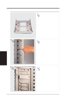
IV. Hardware Setup Hot-Swap Tray Front Connections Seagate Cheetah (ST34501W) side opposite power & SCSI Red White Green Orange Brown Unused 8 4 2 1 Pin 1 Black Activity Signal Blue Yellow Red Pin 2 Black SCSI Address (ID#) The hot-swap tray provides wires for connecting the activity LED, power LED, SCSI ID, power, and SCSI signal. Connect the 8-pin connector to the SCSI Address pins according to the colors shown. Connect the 2-pin connector to the activity signal pins according to the colors shown. NOTE The above is only an example. Always consult your hard disk drive documentation or labels for the exact wiring specific to your hard disk drive make and model. Hot-Swap Tray Interface The front of the hot-swap tray provides a keylock in order to switch the power on, which also locks the handle, and switch the power off, which also releases the handle. Two LEDs provide information on the power and activity status of the hard disk drive. When power is received by the hot-swap tray's connector board, the power LED will light. When data is written or read to or from the contained hard disk drive, the activity LED will flash proportional to the amount of data transferred. Keylock / Power Switch IV. Hardware Setup Hot-Swap Trays Air Inlet Release / Transport Power LED (PLED) Handle Activity LED (SLED) Hot-Swap Tray Face Plate IMPORTANT To place the hot-swap tray into the device bay, you must lift the handle 45 degrees from rest position and then push the tray forcefully. If the tray is snapped in place, the handle can be lowered into place. AP8000 Hardware Reference Guide 27
-
 1
1 -
2
-
3
-
4
-
5
-
6
-
7
-
8
-
9
-
10
-
11
-
12
-
13
-
14
-
15
-
16
-
17
-
18
-
19
-
20
-
21
-
 22
22 -
 23
23 -
 24
24 -
 25
25 -
 26
26 -
 27
27 -
 28
28 -
 29
29 -
 30
30 -
 31
31 -
 32
32 -
33
-
34
-
35
-
36
-
37
-
38
-
39
-
40
-
41
-
42
-
43
-
44
 |
 |
