Asus AP8000 Hardware Reference - Page 31
Separate Config., Cascade Config.
 |
View all Asus AP8000 manuals
Add to My Manuals
Save this manual to your list of manuals |
Page 31 highlights
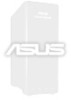
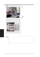
IV. Hardware Setup Using Cascaded SCSI Backplane Boards If installing five or more hard drives in the hot-swap bays, two SCSI backplane boards are required. A two-channel SCSI controller can combine two separate sets of hard drives through software RAID or by using a hardware RAID controller. Cascading the SCSI backplane boards can be done to use only a single channel on the SCSI controller. Separate Config. Cascade Config. Connected to SCSI Controller Top (BP4-1) IV. Hardware Setup SCSI ID Setting (68-pin SCSI) BP4 Cascade Cable Connected to SCSI Controller's Ch2 (or another controller) Bottom (BP4-2) Automatic Termination (no terminator required) When using a cascade configuration, the top SCSI backplane board is referred to as BP4-1 and the bottom SCSI backplane board is referred to as BP4-2, but there are no physical differences. The SCSI hard drives connected on the top SCSI backplane board may select from two sets of SCSI IDs. The SCSI hard drives connected on the bottom SCSI backplane board may only have one set of SCSI IDs. SCSI ID Settings for Cascaded SCSI Backplane Boards Board SET1 SET2 Slot0 Slot1 Slot2 Top ON OFF ID0 ID6 ID8 Top OFF OFF ID1 ID5 ID9 Bottom ON/OFF ON ID3 ID4 ID10 Slot3 ID12 ID13 ID11 AP8000 Hardware Reference Guide 31
-
 1
1 -
2
-
3
-
4
-
5
-
6
-
7
-
8
-
9
-
10
-
11
-
12
-
13
-
14
-
15
-
16
-
17
-
18
-
19
-
20
-
21
-
22
-
23
-
24
-
25
-
 26
26 -
 27
27 -
 28
28 -
 29
29 -
 30
30 -
 31
31 -
 32
32 -
 33
33 -
 34
34 -
 35
35 -
 36
36 -
37
-
38
-
39
-
40
-
41
-
42
-
43
-
44
 |
 |
