Asus Blitz Formula Blitz Formula user's manual E3151 English Edition - Page 108
DRAM Voltage, DRAM Reference Voltage, South Bridge Voltage, PLL, VCORE Voltage
 |
View all Asus Blitz Formula manuals
Add to My Manuals
Save this manual to your list of manuals |
Page 108 highlights
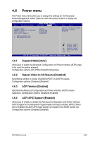
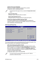
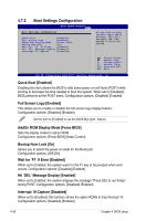
Duty Cycle Mode [90%] Allows you to set the fan duty cycle. When the OPT_Fan1/2 Q-Fan Control item is set to [Q-FAN], this item does not appear. Configuraiton options: [70%] [80%] [90%] [100%] TargetTemp Value [32] Allows you to set the temperature at which the optional fan starts up. When the OPT_Fan1/2 Q-Fan Control item is set to [DUTY CYCLE], this item does not appear. Configuration options: [16] [24] [32] [40] [48] [56] [64] [72] Power Fan Speed [xxxxRPM] or [Ignored] / [N/A] The onboard hardware monitor automatically detects and displays the power fan speed in rotations per minute (RPM). If the fan is not connected to the motherboard, the field shows N/A. VCORE Voltage, FSB Termination Voltage, North Bridge Voltage, DRAM Voltage, DRAM Reference Voltage, South Bridge Voltage, PLL Voltage, 3.3V Voltage, 5V Voltage, 12V Voltage The onboard hardware monitor automatically detects the voltage output through the onboard voltage regulators. 4-34 Chapter 4: BIOS setup
-
 1
1 -
2
-
3
-
4
-
5
-
6
-
7
-
8
-
9
-
10
-
11
-
12
-
13
-
14
-
15
-
16
-
17
-
18
-
19
-
20
-
21
-
22
-
23
-
24
-
25
-
26
-
27
-
28
-
29
-
30
-
31
-
32
-
33
-
34
-
35
-
36
-
37
-
38
-
39
-
40
-
41
-
42
-
43
-
44
-
45
-
46
-
47
-
48
-
49
-
50
-
51
-
52
-
53
-
54
-
55
-
56
-
57
-
58
-
59
-
60
-
61
-
62
-
63
-
64
-
65
-
66
-
67
-
68
-
69
-
70
-
71
-
72
-
73
-
74
-
75
-
76
-
77
-
78
-
79
-
80
-
81
-
82
-
83
-
84
-
85
-
86
-
87
-
88
-
89
-
90
-
91
-
92
-
93
-
94
-
95
-
96
-
97
-
98
-
99
-
100
-
101
-
102
-
 103
103 -
 104
104 -
 105
105 -
 106
106 -
 107
107 -
 108
108 -
 109
109 -
 110
110 -
 111
111 -
 112
112 -
 113
113 -
114
-
115
-
116
-
117
-
118
-
119
-
120
-
121
-
122
-
123
-
124
-
125
-
126
-
127
-
128
-
129
-
130
-
131
-
132
-
133
-
134
-
135
-
136
-
137
-
138
-
139
-
140
-
141
-
142
-
143
-
144
-
145
-
146
-
147
-
148
-
149
-
150
-
151
-
152
-
153
-
154
-
155
-
156
-
157
-
158
-
159
-
160
-
161
-
162
-
163
-
164
-
165
-
166
 |
 |