Asus Blitz Formula Blitz Formula user's manual E3151 English Edition - Page 61
IEEE 1394a port connector 10-1 pin IE1394_2, Thermal sensor cable connectors 2-pin OPT_TEMP1/2
 |
View all Asus Blitz Formula manuals
Add to My Manuals
Save this manual to your list of manuals |
Page 61 highlights
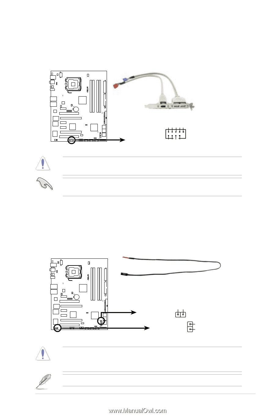
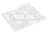
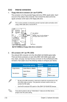
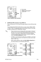
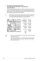
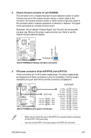
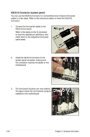
5. IEEE 1394a port connector (10-1 pin IE1394_2) This connector is for a IEEE 1394a port. Connect the IEEE 1394a module cable to this connector, then install the module to a slot opening at the back of the system chassis. ® ® Temperature Ground GND +12V TPB1GND TPA1- +12V TPB1+ GND TPA1+ BLITZ FORMULA IE1394_2 PIN 1 BLITZ FORMULA IEEE 1394a connector Never connect a USB cable to the IEEE 1394a connector. Doing so will damage the motherboard! You can connect the 1394 cable to ASUS Q-Connector (1394, red) first, and then install the Q-Connector (1394) to the 1394 connector onboard. 6. Thermal sensor cable connectors (2-pin OPT_TEMP1/2) These connectors are for temperature monitoring. Connect the thermal sensor cables to these connectors and place the other ends to the devices which you want to monitor temperature. The optional fan1~2 can work with the temperature sensors for a better cooling effect. OPT_TEMP2 BLITZ FORMULA OPT_TEMP1 BLITZ FORMULA Thermal sensor cable connectors Temperature Ground Remove the thermal sensor cable from the assigned device when you set the South Bridge Sensor Select item in BIOS to [SB Overheat Protection]. Refer to page 4-31 for details. The thermal sensor cable is purchased separately. ROG Blitz Formula 2-35
-
 1
1 -
2
-
3
-
4
-
5
-
6
-
7
-
8
-
9
-
10
-
11
-
12
-
13
-
14
-
15
-
16
-
17
-
18
-
19
-
20
-
21
-
22
-
23
-
24
-
25
-
26
-
27
-
28
-
29
-
30
-
31
-
32
-
33
-
34
-
35
-
36
-
37
-
38
-
39
-
40
-
41
-
42
-
43
-
44
-
45
-
46
-
47
-
48
-
49
-
50
-
51
-
52
-
53
-
54
-
55
-
 56
56 -
 57
57 -
 58
58 -
 59
59 -
 60
60 -
 61
61 -
 62
62 -
 63
63 -
 64
64 -
 65
65 -
 66
66 -
67
-
68
-
69
-
70
-
71
-
72
-
73
-
74
-
75
-
76
-
77
-
78
-
79
-
80
-
81
-
82
-
83
-
84
-
85
-
86
-
87
-
88
-
89
-
90
-
91
-
92
-
93
-
94
-
95
-
96
-
97
-
98
-
99
-
100
-
101
-
102
-
103
-
104
-
105
-
106
-
107
-
108
-
109
-
110
-
111
-
112
-
113
-
114
-
115
-
116
-
117
-
118
-
119
-
120
-
121
-
122
-
123
-
124
-
125
-
126
-
127
-
128
-
129
-
130
-
131
-
132
-
133
-
134
-
135
-
136
-
137
-
138
-
139
-
140
-
141
-
142
-
143
-
144
-
145
-
146
-
147
-
148
-
149
-
150
-
151
-
152
-
153
-
154
-
155
-
156
-
157
-
158
-
159
-
160
-
161
-
162
-
163
-
164
-
165
-
166
 |
 |