Asus CP5141 User Manual - Page 12
Side Speaker Out port gray.
 |
View all Asus CP5141 manuals
Add to My Manuals
Save this manual to your list of manuals |
Page 12 highlights
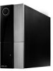
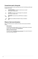
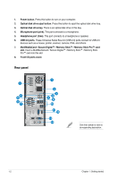
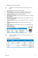
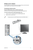
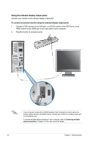
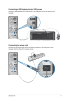
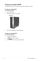
1. Air vents. These vents allow air ventilation. DO NOT block the air vents on the chassis. Always provide proper ventilation for your computer. 2. Power connector. Plug the power cord to this connector. 3. Line Out port (lime). This port connects to a headphone or speaker. In a 4, 6, or 8-channel configuration, the function of this port becomes Front Speaker Out. 4. Microphone port (pink). This port connects to a microphone. 5. Side Speaker Out port (gray). This port connects to the side speakers in an 8-channel audio configuration. 6. Rear Speaker Out port (black). This port connects to the rear speakers in a 4, 6, and 8-channel audio configuration. 7. Line In port (light blue). This port connects to a tape, CD, DVD player, or other audio sources. 8. Center/Subwoofer port (orange). This port connects to the center/subwoofer speakers. 9. LAN (RJ-45) port. This port allows Gigabit connection to a Local Area Network (LAN) through a network hub. LAN port LED indications Activity/Link LED Speed LED ACT/LINK SPEED LED LED Status Description Status Description OFF No link OFF 10Mbps connection ORANGE Linked ORANGE 100Mbps connection BLINKING Data activity GREEN 1Gbps connection LAN port Refer to the audio configuration table below for the function of the audio ports in a 2, 4, 6, or 8-channel configuration. Audio 2, 4, 6, or 8-channel configuration Port Light Blue Lime Pink Orange Black Gray Headset 2-channel Line In Line Out Mic In - - - 4-channel Line In Front Speaker Out Mic In - Rear Speaker Out - 6-channel Line In Front Speaker Out Mic In Center/Subwoofer Rear Speaker Out - 8-channel Line In Front Speaker Out Mic In Center/Subwoofer Rear Speaker Out Side Speaker Out ASUS CP5141 1-3
-
 1
1 -
2
-
3
-
4
-
5
-
6
-
 7
7 -
 8
8 -
 9
9 -
 10
10 -
 11
11 -
 12
12 -
 13
13 -
 14
14 -
 15
15 -
 16
16 -
 17
17 -
18
-
19
-
20
-
21
-
22
-
23
-
24
-
25
-
26
-
27
-
28
-
29
-
30
-
31
-
32
-
33
-
34
-
35
-
36
-
37
-
38
-
39
-
40
-
41
-
42
-
43
-
44
-
45
-
46
-
47
-
48
-
49
-
50
-
51
-
52
-
53
-
54
-
55
-
56
-
57
-
58
-
59
-
60
-
61
-
62
-
63
-
64
-
65
-
66
-
67
-
68
 |
 |