Asus CUW-FX CUW-FX User Manual - Page 36
ASUS CUWE-FX User's Manual, SMBus Connector 5-1 pin SMB, LCD-TV Headers 14-pin LCDTV0/LCDTV1
 |
View all Asus CUW-FX manuals
Add to My Manuals
Save this manual to your list of manuals |
Page 36 highlights
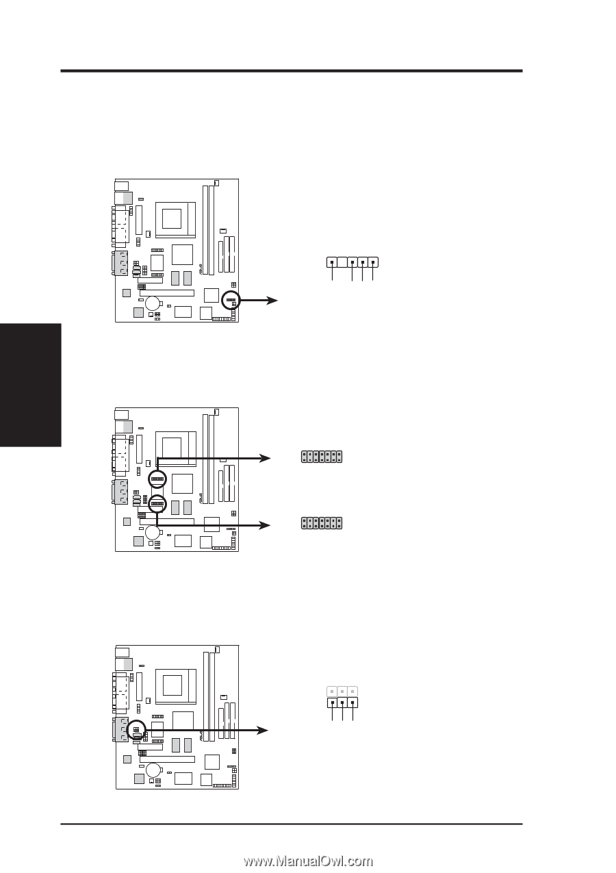
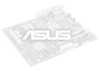
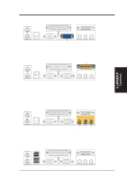
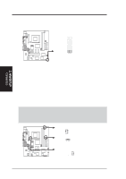
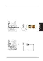
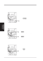
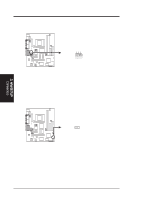
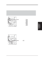
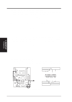
3. HARDWARE SETUP 18) SMBus Connector (5-1 pin SMB) This connector allows you to connect SMBus (System Management Bus) devices. SMBus devices communicate by means of the SMBus with an SMBus host and/or other SMBus devices. SMBus is a specific implementation of an I2C bus, which is a multi-device bus; that is, multiple chips can be connected to the same bus and each one can act as a master by initiating data transfer. CUW(E)-FX ® SMB 1 SMBCLK Ground SMBDATA +5V CUW(E)-FX SMBus Connector 19) LCD-TV Headers (14-pin LCDTV0/LCDTV1) (optional) These headers require an optional LCD module (see 7.1 ASUS LCD-I Controller Module) for LCD output or a TV-out module for TV output. LCDTV0 2 14 1 13 1: GND 2: +1.8V 3: LTVCL 4: LTVDA 5: DMSEN 6: BLANK# 7: TVVSYNC 8: +3V 9: TVHSYNC 10: DD4 11: DD3 12: DD2 13: DD1 14: DD0 ® CUW(E)-FX LCDTV1 2 14 1 13 1: +5V 3: DD10 5: GND 7: DD10 9: DD6 11: CLKOUT0 13: CLKOUT1 2: +5V 4: DD11 6: GND 8: DD11 10: DD7 12: DD9 14: DD5 CUW(E)-FX LCD-TV Headers 20) Internal Microphone Connector (3 pin MIC2) This connector allows you to connect a chassis mounted microphone to the motherboard instead of having to attach an external microphone onto the ATX connectors. 3. H/W SETUP Connectors 1 3 ® MIC Power MIC Input Ground CUW(E)-FX MIC2 CUW(E)-FX Internal Microphone Connector 36 ASUS CUW(E)-FX User's Manual
-
 1
1 -
2
-
3
-
4
-
5
-
6
-
7
-
8
-
9
-
10
-
11
-
12
-
13
-
14
-
15
-
16
-
17
-
18
-
19
-
20
-
21
-
22
-
23
-
24
-
25
-
26
-
27
-
28
-
29
-
30
-
 31
31 -
 32
32 -
 33
33 -
 34
34 -
 35
35 -
 36
36 -
 37
37 -
 38
38 -
 39
39 -
 40
40 -
 41
41 -
42
-
43
-
44
-
45
-
46
-
47
-
48
-
49
-
50
-
51
-
52
-
53
-
54
-
55
-
56
-
57
-
58
-
59
-
60
-
61
-
62
-
63
-
64
-
65
-
66
-
67
-
68
-
69
-
70
-
71
-
72
-
73
-
74
-
75
-
76
-
77
-
78
-
79
-
80
-
81
-
82
-
83
-
84
-
85
-
86
-
87
-
88
-
89
-
90
-
91
-
92
-
93
-
94
-
95
-
96
-
97
-
98
-
99
-
100
-
101
-
102
-
103
-
104
-
105
-
106
-
107
-
108
-
109
-
110
-
111
-
112
-
113
-
114
-
115
-
116
-
117
-
118
-
119
-
120
-
121
-
122
-
123
-
124
-
125
-
126
-
127
-
128
 |
 |