Asus CUW-FX CUW-FX User Manual - Page 37
ASUS CUWE-FX User's Manual, Internal Audio Connectors 4-pin VIDEO, CD1, MODEM, Front Panel USB
 |
View all Asus CUW-FX manuals
Add to My Manuals
Save this manual to your list of manuals |
Page 37 highlights
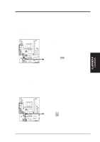
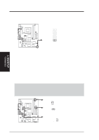
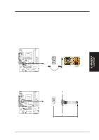
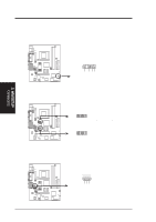
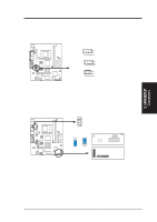
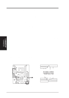
® ® 3. H/W SETUP Connectors 3. HARDWARE SETUP 21) Internal Audio Connectors (4-pin VIDEO, CD1, MODEM) These connectors allow you to receive stereo audio input from such sound sources as a CD-ROM, TV tuner, or MPEG card. The MODEM connector allows the onboard audio to interface with a voice modem card with a similar connector. It also allows the sharing of mono_in (such as a phone) and mono_out (such as a speaker) between the onboard audio and the voice modem card CUW(E)-FX VIDEO (Green) Left Audio Channel Ground Right Audio Channel CD1 (Black) Left Audio Channel Ground Right Audio Channel MODEM Modem-In (to Modem) Ground Modem-Out (from Modem) CUW(E)-FX Internal Audio Connectors 22) Front Panel USB Header (10-1 pin FRONTUSB) If you do not want to use the USB ports on the back panel, a USB header is available midboard. Connect an external connector set to the 10-1 pin block and mount it to the front panel. NOTE: The back and front panel ports cannot be used at the same time. FRONTUSB 61 10 5 6: USB Power 7: USBP3- 8: USBP3+ 9: GND 1: USB Power 2: USBP2- 3: USBP2+ 4: GND 5: NC CUW(E)-FX USBPWR 3 2 1 +5V (Default) 3 2 1 +5VSB USBPWR USB Hub Module FRONTUSB IDELED USB Hub Chip PANEL Front View CUW(E)-FX Front Panel USB and USB Hub Headers Back View If you need additional USB ports, an optional USB hub module is available. Remove the jumpers on the VPANEL connector and connect the module directly to the PANEL and VPANEL connectors. You can then connect an external connector set to the USB Hub header and mount it to either the front or back panel for a total of four USB ports. ASUS CUW(E)-FX User's Manual 37
-
 1
1 -
2
-
3
-
4
-
5
-
6
-
7
-
8
-
9
-
10
-
11
-
12
-
13
-
14
-
15
-
16
-
17
-
18
-
19
-
20
-
21
-
22
-
23
-
24
-
25
-
26
-
27
-
28
-
29
-
30
-
31
-
 32
32 -
 33
33 -
 34
34 -
 35
35 -
 36
36 -
 37
37 -
 38
38 -
 39
39 -
 40
40 -
 41
41 -
 42
42 -
43
-
44
-
45
-
46
-
47
-
48
-
49
-
50
-
51
-
52
-
53
-
54
-
55
-
56
-
57
-
58
-
59
-
60
-
61
-
62
-
63
-
64
-
65
-
66
-
67
-
68
-
69
-
70
-
71
-
72
-
73
-
74
-
75
-
76
-
77
-
78
-
79
-
80
-
81
-
82
-
83
-
84
-
85
-
86
-
87
-
88
-
89
-
90
-
91
-
92
-
93
-
94
-
95
-
96
-
97
-
98
-
99
-
100
-
101
-
102
-
103
-
104
-
105
-
106
-
107
-
108
-
109
-
110
-
111
-
112
-
113
-
114
-
115
-
116
-
117
-
118
-
119
-
120
-
121
-
122
-
123
-
124
-
125
-
126
-
127
-
128
 |
 |
