Asus CUWE CUWE User Manual - Page 16
Layout Contents, H/W SETUP
 |
View all Asus CUWE manuals
Add to My Manuals
Save this manual to your list of manuals |
Page 16 highlights
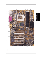
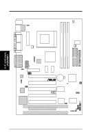
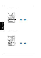
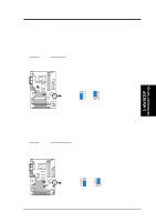
3. HARDWARE SETUP 20) SMB 21) DFP 22) INT MIC 23) CHA 24) ATXPWR 25) SPEAKER (PANEL) 26) KEYLOCK (PANEL) 27) PLED (PANEL) 28) RESET (PANEL) 29) PWRSW (PANEL) 30) SMI (PANEL) 31) LED (PANEL) p.39 SMBus Connector (5-1 pins) p.39 Digital LCD Header (20-1 pins) (optional) p.40 Internal Microphone Connector (3 pins) p.41 Chassis Intrusion Connector (2 pins) p.41 ATX Power Supply Connector (20 pins) p.43 System Warning Speaker Connector (4 pins) p.43 Keyboard Lock Switch Lead (2 pins) p.43 System Power LED Lead (3-1 pins) p.43 Reset Switch Lead (2 pins) p.43 ATX Power / Soft-Off Switch Lead (2 pins) p.43 System Management Interrupt Switch Lead (2 pins) p.43 System Message LED (2 pins) 3. H/W SETUP Layout Contents 16 ASUS CUWE User's Manual
-
 1
1 -
2
-
3
-
4
-
5
-
6
-
7
-
8
-
9
-
10
-
 11
11 -
 12
12 -
 13
13 -
 14
14 -
 15
15 -
 16
16 -
 17
17 -
 18
18 -
 19
19 -
 20
20 -
 21
21 -
22
-
23
-
24
-
25
-
26
-
27
-
28
-
29
-
30
-
31
-
32
-
33
-
34
-
35
-
36
-
37
-
38
-
39
-
40
-
41
-
42
-
43
-
44
-
45
-
46
-
47
-
48
-
49
-
50
-
51
-
52
-
53
-
54
-
55
-
56
-
57
-
58
-
59
-
60
-
61
-
62
-
63
-
64
-
65
-
66
-
67
-
68
-
69
-
70
-
71
-
72
-
73
-
74
-
75
-
76
-
77
-
78
-
79
-
80
-
81
-
82
-
83
-
84
-
85
-
86
-
87
-
88
-
89
-
90
-
91
-
92
-
93
-
94
-
95
-
96
-
97
-
98
-
99
-
100
-
101
-
102
-
103
-
104
-
105
-
106
-
107
-
108
-
109
-
110
-
111
-
112
-
113
-
114
-
115
-
116
-
117
-
118
-
119
-
120
-
121
-
122
-
123
-
124
-
125
-
126
-
127
-
128
-
129
-
130
-
131
-
132
-
133
-
134
-
135
-
136
 |
 |

16
ASUS CUWE User’s Manual
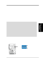
20)
SMB
p.39 SMBus Connector (5-1 pins)
21)
DFP
p.39 Digital LCD Header (20-1 pins) (optional)
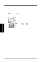
22)
INT MIC
p.40 Internal Microphone Connector (3 pins)
23)
CHA
p.41 Chassis Intrusion Connector (2 pins)
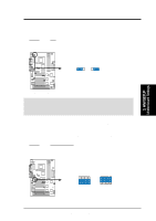
24)
ATXPWR
p.41 ATX Power Supply Connector (20 pins)
25)
SPEAKER (PANEL)
p.43 System Warning Speaker Connector (4 pins)
26)
KEYLOCK (PANEL)
p.43 Keyboard Lock Switch Lead (2 pins)
27)
PLED (PANEL)
p.43 System Power LED Lead (3-1 pins)
28)
RESET (PANEL)
p.43 Reset Switch Lead (2 pins)
29)
PWRSW (PANEL)
p.43 ATX Power / Soft-Off Switch Lead (2 pins)
30)
SMI (PANEL)
p.43 System Management Interrupt Switch Lead (2 pins)
31)
LED (PANEL)
p.43 System Message LED (2 pins)
3. HARDWARE SETUP
Layout Contents
3. H/W SETUP