Asus CUWE CUWE User Manual - Page 38
Standard IR SIR 5-pin and Consumer IR CIR 5-1 pin Connectors
 |
View all Asus CUWE manuals
Add to My Manuals
Save this manual to your list of manuals |
Page 38 highlights
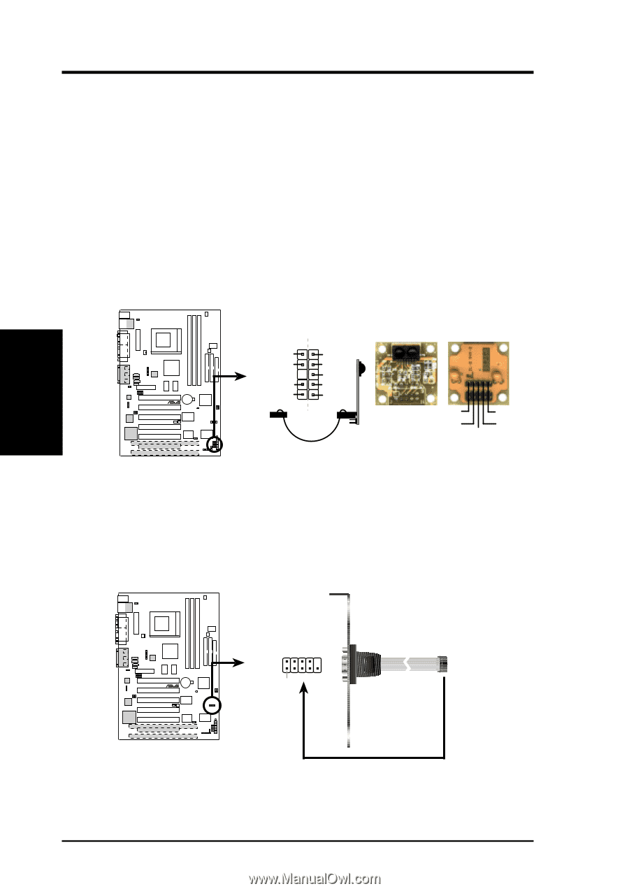
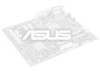
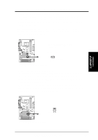
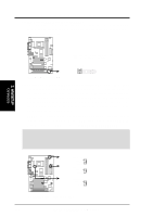
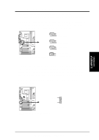
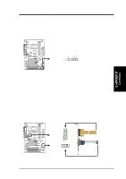
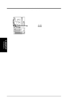
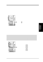
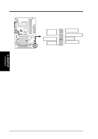
3. H/W SETUP Connectors 3. HARDWARE SETUP 18) Standard IR (SIR) (5-pin) and Consumer IR (CIR) (5-1 pin) Connectors This connector supports an optional wireless transmitting and receiving infrared module. This module mounts to a small opening on system cases that support this feature. You must also configure the setting through UART2 Use Infrared (see 4.4.2 I/O Device Configuration) to select whether UART2 is directed for use with COM2 or IrDA. Use the five pins as shown in Back View and connect a ribbon cable from the module to the motherboard's SIR connector according to the pin definitions. An optional consumer infrared (CIR) set connects to the CIR and SIR connectors simultaneously for both wireless transmitting and remote control functions through one external infrared module. Wake On PS2 KB/Mouse in 4.5.1 Power Up Control must be Enabled in order to use Consumer Infrared (CIR) power up. IR Standard Infrared (SIR) CIR SIR Front View Back View ® CUWE (NC) GND CIRRX CIR+5V +5V (NC) IRRX GND IRTX IRTX +5V GND (NC) IRRX CUWE Infrared Module Connector 19) Serial Port COM 2 Header (10-1 pin COM2) The optional serial port bracket can be used to add an additional serial port for a second serial device. The connector with bracket shown here is for the nonLCD model. 01 01 01 01 01 01 COM2 ® CUWE Pin 1 CUWE Serial COM2 Bracket to COM2 Header 38 ASUS CUWE User's Manual
-
 1
1 -
2
-
3
-
4
-
5
-
6
-
7
-
8
-
9
-
10
-
11
-
12
-
13
-
14
-
15
-
16
-
17
-
18
-
19
-
20
-
21
-
22
-
23
-
24
-
25
-
26
-
27
-
28
-
29
-
30
-
31
-
32
-
 33
33 -
 34
34 -
 35
35 -
 36
36 -
 37
37 -
 38
38 -
 39
39 -
 40
40 -
 41
41 -
 42
42 -
 43
43 -
44
-
45
-
46
-
47
-
48
-
49
-
50
-
51
-
52
-
53
-
54
-
55
-
56
-
57
-
58
-
59
-
60
-
61
-
62
-
63
-
64
-
65
-
66
-
67
-
68
-
69
-
70
-
71
-
72
-
73
-
74
-
75
-
76
-
77
-
78
-
79
-
80
-
81
-
82
-
83
-
84
-
85
-
86
-
87
-
88
-
89
-
90
-
91
-
92
-
93
-
94
-
95
-
96
-
97
-
98
-
99
-
100
-
101
-
102
-
103
-
104
-
105
-
106
-
107
-
108
-
109
-
110
-
111
-
112
-
113
-
114
-
115
-
116
-
117
-
118
-
119
-
120
-
121
-
122
-
123
-
124
-
125
-
126
-
127
-
128
-
129
-
130
-
131
-
132
-
133
-
134
-
135
-
136
 |
 |