Asus DSEB-D16 DSEB-D16 User's Manual for English Edition - Page 38
Memory mirroring and sparing technology, Memory Mirroring
 |
View all Asus DSEB-D16 manuals
Add to My Manuals
Save this manual to your list of manuals |
Page 38 highlights
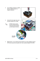
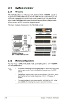
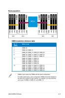
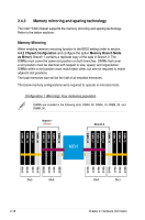
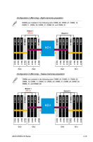
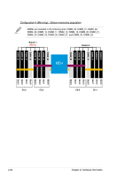
2.4.3 Memory mirroring and sparing technology The Intel® 5400 chipset supports the memory mirroring and sparing technology. Refer to the below sections: Memory Mirroring When enabling memory mirroring function in the BIOS setting (refer to section 4.4.2 Chipset Configuration and configure the option Memory Branch Mode as Mirror), Branch 1 contains a replicate copy of the data in Branch 0. The DIMMs must cover the same slot position on both branches. DIMMs that cover a slot position must be identical with respect to size, speed, and organization. DIMMs within a slot position must match each other, but are not required to match adjacent slot positions. The total memories size will be the half of all installed memories. The below memory configurations were required to operate in mirrored mode. Configuration 1 (Mirroring): Four memories population DIMMs are installed in the following slots: DIMM_00, DIMM_10, DIMM_20, and DIMM_30. Branch 1 (Mirror) Branch 0 DIMM_20 DIMM_21 DIMM_22 DIMM_23 DIMM_30 DIMM_31 DIMM_32 DIMM_33 MCH DIMM-13 DIMM-12 DIMM_11 DIMM_10 DIMM_03 DIMM_02 DIMM_01 DIMM_00 Slot 3 Slot 2 Slot 1 Slot 0 Slot 3 Slot 2 Slot 1 Slot 0 Slot 0 Slot 1 Slot 2 Slot 3 Slot 0 Slot 1 Slot 2 Slot 3 Ch:3 Ch:2 2-18 Ch:0 Ch:1 Chapter 2: Hardware information
-
 1
1 -
2
-
3
-
4
-
5
-
6
-
7
-
8
-
9
-
10
-
11
-
12
-
13
-
14
-
15
-
16
-
17
-
18
-
19
-
20
-
21
-
22
-
23
-
24
-
25
-
26
-
27
-
28
-
29
-
30
-
31
-
32
-
 33
33 -
 34
34 -
 35
35 -
 36
36 -
 37
37 -
 38
38 -
 39
39 -
 40
40 -
 41
41 -
 42
42 -
 43
43 -
44
-
45
-
46
-
47
-
48
-
49
-
50
-
51
-
52
-
53
-
54
-
55
-
56
-
57
-
58
-
59
-
60
-
61
-
62
-
63
-
64
-
65
-
66
-
67
-
68
-
69
-
70
-
71
-
72
-
73
-
74
-
75
-
76
-
77
-
78
-
79
-
80
-
81
-
82
-
83
-
84
-
85
-
86
-
87
-
88
-
89
-
90
-
91
-
92
-
93
-
94
-
95
-
96
-
97
-
98
-
99
-
100
-
101
-
102
-
103
-
104
-
105
-
106
-
107
-
108
-
109
-
110
-
111
-
112
-
113
-
114
-
115
-
116
-
117
-
118
-
119
-
120
-
121
-
122
-
123
-
124
-
125
-
126
-
127
-
128
-
129
-
130
-
131
-
132
-
133
-
134
-
135
-
136
-
137
-
138
-
139
-
140
-
141
-
142
-
143
-
144
-
145
-
146
-
147
-
148
-
149
-
150
-
151
-
152
-
153
-
154
-
155
-
156
-
157
-
158
-
159
-
160
-
161
-
162
-
163
-
164
-
165
-
166
-
167
-
168
-
169
-
170
-
171
-
172
-
173
-
174
-
175
-
176
-
177
-
178
-
179
-
180
-
181
-
182
-
183
-
184
-
185
-
186
-
187
-
188
-
189
-
190
-
191
-
192
-
193
-
194
-
195
-
196
-
197
-
198
-
199
-
200
 |
 |