Asus E500-CI CUW-RM User Manual - Page 16
ASUS CUW-RM User's Manual
 |
View all Asus E500-CI manuals
Add to My Manuals
Save this manual to your list of manuals |
Page 16 highlights
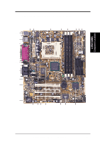
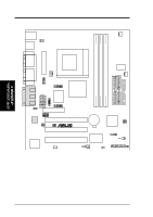
3. HARDWARE SETUP 23) JTPWR 24) PLED (PANEL) 25) KEYLOCK (PANEL) 26) SPEAKER (PANEL) 27) RESET (PANEL) 28) PWR (PANEL) 29) EXTSMI (PANEL) 30) LED (PANEL) p.41 Thermal Sensor Connector (2 pins) p.42 System Power LED Lead (3-1 pins) p.42 Keyboard Lock Switch Lead (2 pins) p.42 System Warning Speaker Connector (4 pins) p.42 Reset Switch Lead (2 pins) p.42 ATX Power / Soft-Off Switch Lead (2 pins) p.42 System Management Interrupt Switch Lead (2 pins) p.42 System Message LED (2 pins) 3. H/W SETUP Layout Contents 16 ASUS CUW-RM User's Manual
-
 1
1 -
2
-
3
-
4
-
5
-
6
-
7
-
8
-
9
-
10
-
 11
11 -
 12
12 -
 13
13 -
 14
14 -
 15
15 -
 16
16 -
 17
17 -
 18
18 -
 19
19 -
 20
20 -
 21
21 -
22
-
23
-
24
-
25
-
26
-
27
-
28
-
29
-
30
-
31
-
32
-
33
-
34
-
35
-
36
-
37
-
38
-
39
-
40
-
41
-
42
-
43
-
44
-
45
-
46
-
47
-
48
-
49
-
50
-
51
-
52
-
53
-
54
-
55
-
56
-
57
-
58
-
59
-
60
-
61
-
62
-
63
-
64
-
65
-
66
-
67
-
68
-
69
-
70
-
71
-
72
-
73
-
74
-
75
-
76
-
77
-
78
-
79
-
80
-
81
-
82
-
83
-
84
-
85
-
86
-
87
-
88
-
89
-
90
-
91
-
92
-
93
-
94
-
95
-
96
-
97
-
98
-
99
-
100
-
101
-
102
-
103
-
104
-
105
-
106
-
107
-
108
-
109
-
110
-
111
-
112
-
113
-
114
-
115
-
116
-
117
-
118
-
119
-
120
-
121
-
122
-
123
-
124
-
125
-
126
-
127
-
128
 |
 |

16
ASUS CUW-RM User’s Manual
3. HARDWARE SETUP
Layout Contents
3. H/W SETUP
23)
JTPWR
p.41 Thermal Sensor Connector (2 pins)
24) PLED (PANEL)
p.42 System Power LED Lead (3-1 pins)
25) KEYLOCK (PANEL)
p.42 Keyboard Lock Switch Lead (2 pins)
26)
SPEAKER (PANEL)
p.42 System Warning Speaker Connector (4 pins)
27) RESET (PANEL)
p.42 Reset Switch Lead (2 pins)
28) PWR (PANEL)
p.42 ATX Power / Soft-Off Switch Lead (2 pins)
29)
EXTSMI (PANEL)
p.42 System Management Interrupt Switch Lead (2 pins)
30) LED (PANEL)
p.42 System Message LED (2 pins)