Asus ESC500 G2 User Manual - Page 34
Installing 5.25-inch drives
 |
View all Asus ESC500 G2 manuals
Add to My Manuals
Save this manual to your list of manuals |
Page 34 highlights
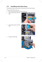
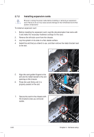
2.6 Installing 5.25-inch drives Ensure to unplug the power cable before installing or removing any system components. Failure to do so may cause severe damage to the motherboard and other system components! The system comes with three 5.25-inch drive bays located on the upper front part of the chassis. An optical drive that comes standard/optional with the system 1 package occupies the uppermost bay (labeled 1). The lower bays (labeled 2 2 and 3) are available for additional 5.25inch optical, zip, or floppy disk drives. 3 You must remove the front panel assembly before installing a 5.25-inch drive. 2.6.1 Removing the front panel cover To remove the front panel cover 1. Follow the instructions in section 2.1 Chassis cover to remove the side cover. Locate the front panel assembly lock, then move it outward to unlock the front panel. 2. Gently lift the front panel assembly until the hinge-like tabs on the top side of the assembly are detached from the chassis. 3. Remove the front panel assembly, then set aside. 2-16 Chapter 2: Hardware setup
-
 1
1 -
2
-
3
-
4
-
5
-
6
-
7
-
8
-
9
-
10
-
11
-
12
-
13
-
14
-
15
-
16
-
17
-
18
-
19
-
20
-
21
-
22
-
23
-
24
-
25
-
26
-
27
-
28
-
 29
29 -
 30
30 -
 31
31 -
 32
32 -
 33
33 -
 34
34 -
 35
35 -
 36
36 -
 37
37 -
 38
38 -
 39
39 -
40
-
41
-
42
-
43
-
44
-
45
-
46
-
47
-
48
-
49
-
50
-
51
-
52
-
53
-
54
-
55
-
56
-
57
-
58
-
59
-
60
-
61
-
62
-
63
-
64
-
65
-
66
-
67
-
68
-
69
-
70
-
71
-
72
-
73
-
74
-
75
-
76
-
77
-
78
-
79
-
80
-
81
-
82
-
83
-
84
-
85
-
86
-
87
-
88
-
89
-
90
-
91
-
92
-
93
-
94
-
95
-
96
-
97
-
98
-
99
-
100
-
101
-
102
-
103
-
104
-
105
-
106
-
107
-
108
-
109
-
110
-
111
-
112
-
113
-
114
-
115
-
116
-
117
-
118
-
119
-
120
-
121
-
122
-
123
-
124
-
125
-
126
-
127
-
128
-
129
-
130
-
131
-
132
-
133
-
134
-
135
-
136
-
137
-
138
-
139
-
140
 |
 |
