Asus ESC500 G2 User Manual - Page 36
Connect a 7-pin SATA cable from, pin power plug from the power
 |
View all Asus ESC500 G2 manuals
Add to My Manuals
Save this manual to your list of manuals |
Page 36 highlights
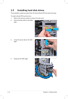
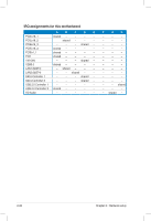
5. Connect a 7-pin SATA cable (from the motherboard SATA port) and a 15-pin power plug (from the power supply unit) to the back connectors of the hard disk drive. 6. Reinstall the front panel cover and side covers when done. Use either the 15-pin SATA power connector OR the legacy 4-pin power connector. DO NOT use both to prevent damage to components and to keep the system from becoming unstable. 2-18 Chapter 2: Hardware setup
-
 1
1 -
2
-
3
-
4
-
5
-
6
-
7
-
8
-
9
-
10
-
11
-
12
-
13
-
14
-
15
-
16
-
17
-
18
-
19
-
20
-
21
-
22
-
23
-
24
-
25
-
26
-
27
-
28
-
29
-
30
-
 31
31 -
 32
32 -
 33
33 -
 34
34 -
 35
35 -
 36
36 -
 37
37 -
 38
38 -
 39
39 -
 40
40 -
 41
41 -
42
-
43
-
44
-
45
-
46
-
47
-
48
-
49
-
50
-
51
-
52
-
53
-
54
-
55
-
56
-
57
-
58
-
59
-
60
-
61
-
62
-
63
-
64
-
65
-
66
-
67
-
68
-
69
-
70
-
71
-
72
-
73
-
74
-
75
-
76
-
77
-
78
-
79
-
80
-
81
-
82
-
83
-
84
-
85
-
86
-
87
-
88
-
89
-
90
-
91
-
92
-
93
-
94
-
95
-
96
-
97
-
98
-
99
-
100
-
101
-
102
-
103
-
104
-
105
-
106
-
107
-
108
-
109
-
110
-
111
-
112
-
113
-
114
-
115
-
116
-
117
-
118
-
119
-
120
-
121
-
122
-
123
-
124
-
125
-
126
-
127
-
128
-
129
-
130
-
131
-
132
-
133
-
134
-
135
-
136
-
137
-
138
-
139
-
140
 |
 |

Chapter 2:
Hardware setup
2-18
Use either the 15-pin SATA power connector OR the legacy 4-pin power
connector. DO NOT use both to prevent damage to components and to keep
the system from becoming unstable.
5.
Connect a 7-pin SATA cable (from
the motherboard SATA port) and a
15-pin power plug (from the power
supply unit) to the back connectors
of the hard disk drive.
6.
Reinstall the front panel cover and
side covers when done.